


Instruction Manual
748374-F
March 2003
4-2 Maintenance and Troubleshooting Rosemount Analytical Inc. A Division of Emerson Process Management
Model NGA2000 TO2
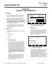
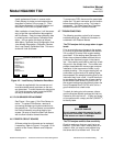
a. Water Addition
To add water:
1. Remove the top cover of the analyzer
module.
2. Unscrew the black sensor cover.
3. Slide the cover back just enough to al-
low the neck of the fill bottle to fit into
the sensor reservoir.
4. Add distilled or deionized water using
the fill bottle provided with the analyzer
module. Fill to approximately midway
between the min and max level indica-
tors on the sensor label. Be careful not
to spill water, splash electrolyte or over-
fill sensor.
5. Replace the sensor cover securely.
6. Replace the top cover of the analyzer
module.
If the electrolyte alarm is activated but the
sensor shows sufficient electrolyte, the elec-
trolyte may have been contaminated by
substances present in the sample which are
chemically incompatible with the sensor or
electrolyte. If this should occur, the electro-
lyte must be drained and replaced with
fresh electrolyte.
Refer to Section 4-3 below for the proper
procedure for replacing electrolyte.
Several other components may require re-
placement. These are discussed in the fol-
lowing sections.
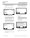
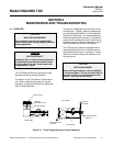
4-2 FUSES
Remove power to the Analyzer Module prior to
fuse replacement. To replace the Power Fuse,
locate the fuse cover on the front panel of the
Analyzer Module, as shown partially in Figure
2-3 on page 2-4. Push and turn the fuseholder
cover 1/4 turn counterclockwise. Remove and
replace the fuse as required. There are no
other fuses in the Analyzer Module.
4-3 ELECTROLYTE REPLACEMENT
Before replacing the electrolyte, be sure to turn
off and disconnect all gas connections to the
analyzer module. Turn off or disconnect the
power to the analyzer module.
To replace the Sensor electrolyte, remove the
Analyzer Module from its mounting location and
place on a sturdy work surface. Be careful not
to tilt the module from its horizontal position as
the Sensor contains liquid that can spill. Re-
move the cover of the Analyzer Module and lo-
cate the 5 mounting screws that hold the Sensor
Assembly onto the Analyzer Module chassis
(see Figure 4-1 on page 4-1). Remove the 5
screws and retain. Do not lose the screws - they
have metric threads.
Disconnect the Sensor signal connector (J5)
and the Flow Sensor connector (J6) from the
power board. Remove the complete Sensor
Assembly from the Analyzer Module. Remove
the black sensor cover and invert the Sensor
Assembly over a suitable receptacle. Flush the
Sensor twice with deionized water. Dispose of
the discarded electrolyte and rinse water in ac-
cordance with National, Federal, State and Lo-
cal regulations. (See MSDS in the rear of this
manual.)
Refill the Sensor with electrolyte as instructed in
Section 2-2a on page 2-1. Reinstall the Sensor
Assembly and reconnect J5 and J6 to the power
board.
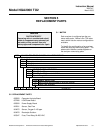
4-4 SENSOR REPLACEMENT
If the Sensor cannot be regenerated by the ad-
dition of water or the replacement of electrolyte,
or if the Sensor shows signs of leakage, it may
be necessary to replace the Sensor. To replace
the Sensor, remove the Sensor Assembly and
remove the electrolyte as described in Section
4-3 above. Reinstall the black sensor cover to
catch any residual electrolyte. Invert the Sensor
Assembly and locate the four (4) mounting
screws which hold the Sensor to the Sensor As-
sembly mounting plate. Remove and retain the
four screws.