


TESTING & SERVICE
(continued)
3 --- 2
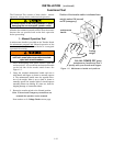
MANUAL LOAD TRANSFER
This procedure will manually transfer the load if the
Controller is disconnected.
Do not manually operate the transfer switch
until both power sources are disconnected.
1. Open normal and emergency source circuit breakers.
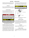
2. Use manual handle to manually operate transfer
switch to the opposite source. If detachable, remove
the handle. See Section 1, Manual Operation.
3. If the transf er switch is in the Emergency position
manually start the engine generator and t h en close
the emergency source circuit breaker.
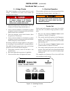
TROUBLE-SHOOTING
Note the Control Features that are activated or furnished
on the switch and review their operation. Refer to
Section 5, Optional Features.
Proceed with care! The ASCO 386 is energized.
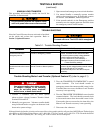
Table 3-1. Trouble-Shooting Checks.
P
R
O
B
L
E
M
CHECK IN NUMERICAL SEQUENCE
P
R
O
B
L
E
M
1OPERATION 2VOLTAGE
Transfer switch does not
transfer the load to the
emergency source.
Turn Transfer Control switch clockwise to
Transfer to Emergency position.
Generator ouput circuit bre aker must be
closed. Voltmeter should read at least 90%
of nominal phase t o phase voltage between
transfer switch terminals EA and EC
(or EL1 and EL2 for 2 pole switches). *
Generator frequency must be at least 57 Hz. *
* These are factory settings.
Transfer switch does not
transfer the load to the normal
source.
Turn Transfer Control switch counterclock-
wise to Transfer to Normal position.
Voltmeter should read at leas t 90% of nominal
phase to phase voltage between transfer switch
terminals NB and NC, NC and NA,
and NA and NB (or NL1 and NL2 for 2 pole
switches).
Trouble-Shooting Motor Load Transfer (Optional Feature 27) (refer to page 5-1)
Use extreme caution when using a meter
to measure voltages in the following
steps. Do not touch power terminals;
sh oc k , burns , or d e at h could result !
1. Connect a voltmeter (set for twice system
phase-to-phase voltage) between Transfer Switch
terminals NA and EA.
2. Manually start generator. Voltmeter needle should
sweep back and forth at a regular rate between 0 and
about twice system voltage.
3. Turn the TRANSFER TO EMERGENCY control
switch clockwise. The load should transfer to
emergency source when meter needle i s near 0 volts.
If transfer does not occur, the Motor L oad Transfer
accessory is not operating.
4. Turn the TRANSFER TO NORMAL control switch
counterclockwise. The load should retransfer back
to the normal source when the needle is near 0 volts.
If retransfer does not occur after the time delay, the
Motor Load Transfer accessory is not operating.
5. Disconnect the voltmeter.
Ifthe problemisisolatedto circuitsonthe controllerorthe transferswitch, callyour localASCOPowerTechnologies
sales offi ce or ASI. In t he Unite d Stat es, call 1–800–800–2726. In Canada , call 1–888–234–2726. Furni sh the Se rial
No., Bi ll of Ma teria l (B OM) No., & Cata log No. from transfer switch nameplate.