


SECTION 3
TESTING & SERVICE
3 --- 1
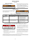
PREVENTIVE MAINTENANCE
Reasonable care in preventive maintenance will insure
high reliability and long life for the switch. An annual
preventive maintenance program is recommended.
ASCO Services, Inc. (ASI) is ASCO P ower
Technologies’s national service organization. ASI
can be contacted at 1-800-800-2726 for information
on preventive maintenance agreements. In Canada
call 1–888–234–ASCO (2726).
TESTING
Operate the switch at least once a month by followingthis
four-step Electrical Operation Test.
Transfer Switch Test
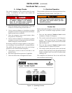
A. Turn the door-mounted Tr an sfer Con trol switch
clockwise to Transfer to Emergency.
B. The transfer switch will operate to the Emergency
position. The Load Connected To Em ergency light
should come on and the Load Connected to Normal
lig ht s hould go off.
C. Turn the door-mounted Tr an sfer Con trol switch
counterclockwise to Transfer to Normal.
D. The transfer switch will operate to the Normal posi-
tion. The Load Connected to Normal light should come
on a nd th e Loa d Connected to Emergency light should
go off.
Checklist f or Yearly Inspection
Hazardous voltage capable of causing shock,
burns, or death is used in this switch.
Deenergize both Normal & Emergency po wer
sources before performing inspections!
❐ Clean the switch enclosure. Brush and vacuum away
any excessive dust accumulation. Remove any mois-
ture with a clean cloth.
❐ Check the Switch Contacts
.Removetransferswitch
barriers and check the condition of the contacts. Re-
place contacts when pitted or worn excessively. Re-
install barriers carefully.
❐ Maintain transfer switch lubrication.Ifswitchis
sub jec ted to severe dust or ab norm al operating c on-
ditions, renew factory lub ric ation on all movem en ts
and lin ka g es . Re l u b r ic ate solen o id oper ato r if TS
co il is repl aced . D on ’t use oil; ord er lubrication
625550–001 (Castrol EndurexR 4000 lubricant).
❐ Check all cable connections and retighten them.
REPLACEMENT PARTS
Replacement parts are available in kit form. When or-
dering parts provide the Serial No., Bill of Material No.
(BOM), and Catalog No. from the transfer switch name-
plate. Contact your local ASCO Power Technologies
sales office or ASI. In the United States call
1–800–800–ASCO (2726), or in Canada call
1–888–234–ASCO (2726).
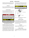
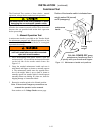
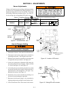
DISCONNECTING T HE CONTROLLER
The harness disconnect plugs are furnished for repair
purposes only and should not have to be unplugged. If
the controller must be isolated, follow these steps:
Disconnecting the Plugs
Do not unplug the controller until
step 1a. o r 1b. below is completed.
1. Observe the position of the transfer switch.
a. If the transfer s w itc h is in the Normal position, place
stand b y engine starting contr o l in the off position.
Then open the emergency source circuit breaker.
b. If the transfer switch is in the Emergency position,
open the normal source circuit breaker. Place the
engine starting control in the test or run position.
2. Separate the quick disconnect plugs by squeezing the
latches. Do not pull on the harness wires.
Reconnecting the Plugs
Do not reconnect controller until
steps 1 and 2 below are completed.
1. Observe the position of the transfer switch.
a. If the transfer switch is in the Normal position, be
sure that the standby engine starting control is
still in the off position. The emergency source cir-
cuit breaker still should be open.
b. If trans fe r s w itch is in the Emergency position, nor-
mal source circuit breaker still should be open.
2. The harness plugs and sockets are keyed. Carefully
align the plugs with the sockets and press straight in
until both latches click.
3. Restore the opposit e source as follows:
a. If the transfer switch is i n the Normal position,
place the standby engine starting control in the
automatic position. Then close the emergency
source circuit breaker.
b. If the transfer switch is in the Emergency position,
close the normal source circuit breaker.