


SECTION 1 INSTALLATION
1 --- 1
ASCO 386 Non–Automatic Transfer Switches are factory
wired and tested. Installation requires skid removal then
securing the enclosure to the supporting foundatio n.
Mounting
Refer to the applicable enclosure outline drawing fur-
nished with this switch and mount the Series 300
according to details and instructions shown on diagram.
Line Connections
Refer to the Wiring Diagram provided with your ASCO
386 N–ATS. All wiring must be m ade in accordance with
the National Electrical Code and local codes.
It is unnecessary to remove pole covers from the transfer
switch. If you do remove them, reinstall them carefully.
De–energize the conductors before making any
line or auxiliary circuitry connections. Be sure
that Normal and Emergency line connections
are in proper phase rotation. Place engine gen-
erator starting control in the OFF position. Make
sure engine generator is not in operation.
Protect the non–automatic transfer switch from
construction grit and metal chi ps to prevent
malfunction or shortened life of the N–ATS.
Connecting Power Conductors
After the power cables have been tested, connect them to
the appropriate t erminal lugs on the transfer switch as
shown on the wiri ng diagram provided with this ASCO
386. Make sure t he lugs provided are suitable for use with
the cables being installed. Standard terminal lugs are
solderless screw type and will accept the wire sizes listed
on the drawings provided with the ASCO 386. Be careful
when stripping insulati on from the cables; avoi d nicking
or ringing the conductor. Remove surface oxides from
cables by cleaning with a wire brush. When aluminum
cable is used, apply joint compound to conductors.
Tighten cable lugs to the torque specified on rating label.
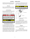
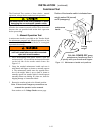
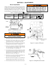
Three cable spacers are included with 150, 200, and 230
ampere transfer switches. When installing power cables,
run the cables through the cable spacers as shown in
Figure 1–1. Position cable spacers withi n 1½ inches from
lugs.
The cable spacers must be located as shown
for 150, 200, and 230 ampere transfer switches.
cable spacer
cable spacers
1 ½ inch approximate
Figure 1–1. Cable spacers for 150, 200, & 230 amp.
transfer switches.
Controller Ground
A grounding wire must be connected to the controller’s
lower left mounting stud. Because the controller is
mounted on the enclosure door, a conductive strap must
be used between the e nclosure and the door. This
connection provides proper grounding which does not
rely upon the door hinges.
Harnesses
The transfer switch is connected to the left side of the
controller by a plug–in harness (two plugs).
Auxiliary Circuits
Connect auxiliary circuit wires to appropriate terminals
on transfer switch as shown o n the wiring diagram
provided with this ASCO 386 Non–Automatic Transfer
Switch.