


INSTALLATION (continued)
1 --- 3
Functional Test (continued)
2–VoltageChecks
First check nameplate on the transfer switch for rated
voltage. It should be the same as the normal and
emergency line voltages.
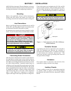
Use extreme caution when using a meter
to measure voltages in the following
steps. Do not touch power terminals;
sh oc k , burns , or d e at h could result !
1. Close the normal source circuit breaker. The Load
Connected To Normal lamp should come on.
2. Use an accurate voltmeter to check phase to phase
and phase to neutral voltages present at the Transfer
Switch normal source terminals.
3. Close the emergency source circuit breaker. (Start
the generator, if necessary.)
4. Use an accurate voltmeter to check phase to phase
and phase to neutral voltages present at the Transfer
Switch emergency source terminals.
If necessary, adjust the voltage regulator on the genera-
tor according to the manufacturer’s recommendations.
The ASCO 386 wi ll respond only to the rated voltage
specified on the Transfer Switch nameplate.
5. Check phase rotation; i t must be the same as the
normal source.
6. Shut down engine-driven generator, if applicable.
7. Close the cabinet door and t ighten the screws.
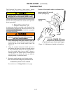
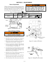
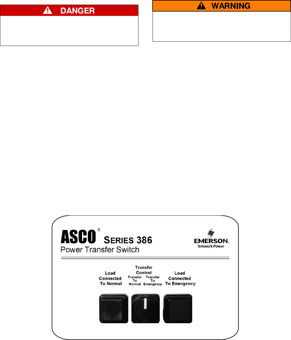
3 – Electrical Operation
This procedure will check the electrical operation of the
Non-Automatic Transfer Switch. See Figure 1–3.
Close the transfer switch enclosure door
and tighten the screws before you test
electrical operation.
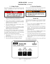
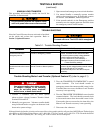
Transfer Test
Both normal and emergency sources must be available
and above 90% of nominal voltage specified on name-
plate.
1. Turn the door-mounted Tra ns fer Co ntro l switch
clockwise to Transfer To Emergency.
2. The transfer switch will operate to the Emergency
position. The Load Connected To Emergency light
should come on and the Load Connected To Normal
light should go off.
3. Turn the door-mounted Tra ns fer Co ntro l switch
counterclockwise to Transfer To Normal.
4. The transfer switch will operate back to the Normal
position. The Load Connected to Normal light should
come on and the Load Connect ed To Emergency light
should go off.
This completes the Functional Test of the ASCO 386
non-automatic transfer switch.
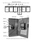
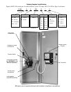
Figure 1–3. Operating Controls.