


INSTALLATION (continued)
1 --- 2
Functional Test
The Functional Test consists of three checks: manual
operation, voltage checks, and electrical operation.
Do these checks in the order presented to avoid
damaging the non–automatic transfer switch.
Read all instructions on the Wiring Diagram and labels
affixed to the automatic transfer switch. Note the control
features that are provided and review their operation
before proceeding.
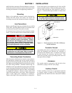
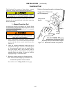
1 – Manual Operation Test
A maintenance handle is provided on the Transfer Switch
for maintenanc e purpos es only
. Manual operation of the
transfer switch should be checked before it is energized
(operated electrically).
Do not manually operate the transfer switch
until both power sources are disconnected:
open both circuit breakers.
1. After deenergizing both power sources, open the
enclosure door. Locate a nd the mai ntenance handle
on the left side of the transfer switch frame. See
Figure 1–2.
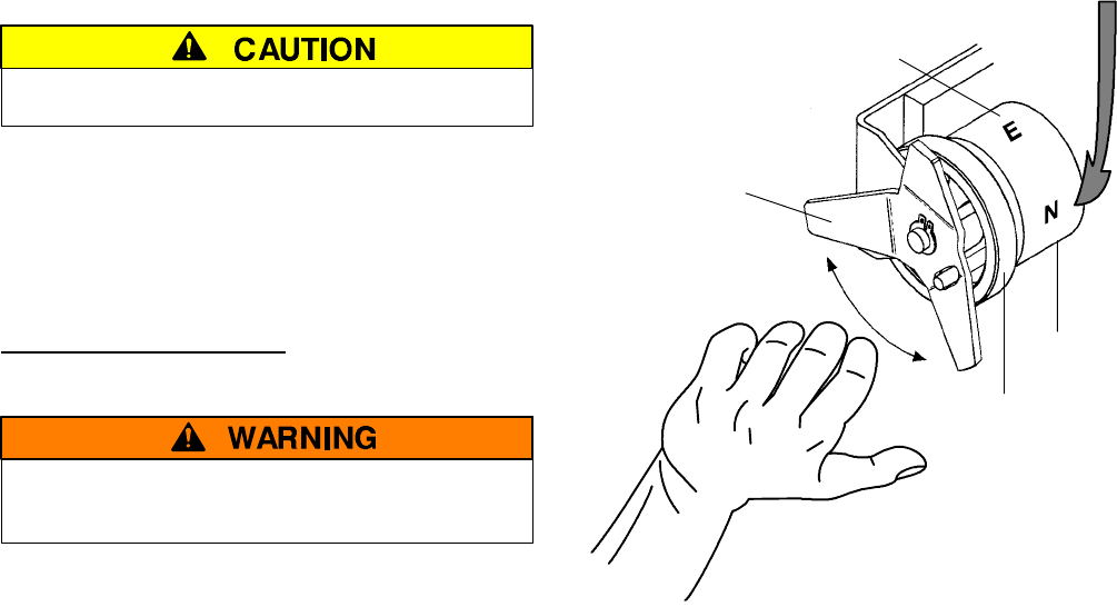
2. Gras p the attached mainten ance handl e and tu rn it
with thum b and fing ers as shown to manual ly operate
it. The maintenance handle turns the opposite direc-
tion of the w eight. Move it up or dow n as show n to
manu all y op erate the trans fer s witch. It s houl d operate
smoothly w ithout any b inding. If it does n ot, check for
shipping dam age or construction debris.
3. Retur n the transfer switch to the Norm al pos ition.
Note: If Normal and Emergency connections are
reversed this operation is also reversed.
Now continue to 2–VoltageCheckson next page.
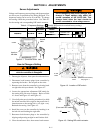
maintenance
handle
With ALL POWER OFF grasp
maintenance handle and turn it
quickly with your thumb and fingers.
weight marked N (normal)
and E (emergency)
floating
weight
weight
P osition of the tr ansf er switch i s in di cate d h er e
Figure 1–2. Maintenance handle and positions.