


SECTION 2
SEQUENCE OF OPERATION
2 --- 1
Controller Code 1
Refer to Section 5, Optional Accessories for additional control functions.
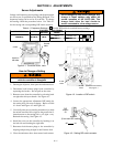
Refer to Wiring Diagram furnished with the ASCO 386. Note Control Features furnished on this switch, and review operation.
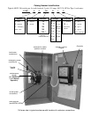
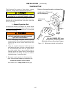
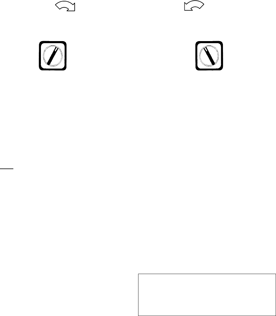
Transfer
Control
Transfer
To
Normal
Transfer
To
Emergency
Transfer To Emergency
The sequence for load transfer to the emergency
sour ce begins whe n y ou tur n t he door -m ounted
Tran sfer Con tro l switch clockwise to the Transfer To
Emergency position.
When the Transfer Co n trol switch is operated to
Tr a ns fer To Emer genc y, the voltage and frequency
sensor begins monitoring the emergency source.
The sensor will accept the emergency source only
when both
voltage and frequency reach preset
pickup points. If the emergency source is available
immediately, the sensor may accept it as soon as the
Transfer Control switch is operated.
When the emergency source is accepted by the
sensor, relay ER picks up to transfer the load to the
emergency source.
ER relay energizes, the TS coil is energized, the
transfer switch operates, and all switch contacts
(mains, controls, auxiliaries) reverse position. The
transfer switch is now supplying the load from the
emergency source.
ThetransferswitchwillremainintheEmergency
position until the Transfer Contro l switchis operated
to the Transfer To Normal position.
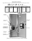
Transfer
Control
Transfer
To
Normal
Transfer
To
Emergency
Retransfer to Normal
The sequence for load retransfer to the normal
source begins when you turn t he door-mounted
Tran sfer Con trol switch counterclockwise to the
Transfer To Normal position.
When the Transfer Co ntro l switch is operated to
Transfer To No rmal, the voltage sensor begins
monitoring the normal source.
The SE relay energizes when the sensor accepts the
normal source voltage.
SE relay energizes. The TS coil is energized, the
transfer switch operates, and all switch contacts
(mains, controls, auxiliaries) reverse position. The
transfer switch is now supplying the load from the
normal source again.
The SE relay de–energizes when the Tra nsfer
Control switch is released.
ThetransferswitchwillremainintheNormal
position until the Transfer Contro l switch is operated
to the Tr a n sfer To Emergen c y position.
Note
Activation of standard control features shown
in Section 5 will alter the sequence of
operation and introduce additional time
delays during transfer operations.