


SECTION 4 ADJUSTMENTS
4 --- 1
Sensor Adjustments
Vo ltage and frequency sensor pickup and dropout points
are factory set as specified on the Wiring Diagram. The
frequency setting can be set for 50 or 60 Hz.. To change
this setting, follow the procedure below. Use Table 4-1
for the setting and corresponding DIP switch actuator.
Do not change any other factory settings. Any
change in these settings may affect the
normal o peration of the ASCO 386. This
change could allow the load circuits to
remain connected to a low voltage source.
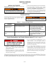
Table 4-1. Frequency Settings. (
Shaded DIP switch is standard factory setting).
DESCRIPTION LABEL
FACTORY
SETTING
ADJUSTMENT
RANGE
S1 DIP SWITCH
F
r
e
q
u
e
n
c
y
6
0
/
5
0
H
z
6
0
H
z
60 Hz Actuator 4 off
4
F
requency 60
/
50
H
z 60
H
z
50 Hz Actuator 4 on
4
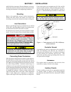
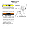
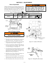
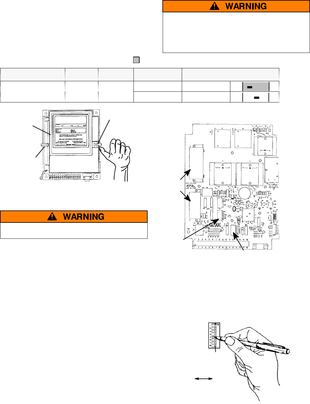
thumb
latch
cover
hook on
left side
Figure 4-1. Controller cover latch.
How to Change a Setting
Do not make any setting changes
while the controller is energized.
1. Deenergize all power, then open the enclosure door.
2. Disconnect both harness plugs from controller by
squeezing the latches. Do not pull on the wires.
3. Remove cover from the controller by releasing latch
on right side with your thumb. See Figure 4-1.
4. Locate the appropriate adjustment DIP switch for
the setting that you want to change. Refer to Table
4-1 above and Figure 4-2 and Figure 4-3.
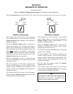
5. Use a ball-point pen (or similar pointed tool) to slide
the switch actuators left or right so they match the i l-
lustration next to the setting (left = off, right = on).
Recheck the setting. See Figure 4-3.
6. Install the cover on the controller by hooking it on
the left si de and latching the right side.
7. Reconnect both harness plugs to the controller by
aligning and pressing straight in until latches click.
8. Close the enclosure door, then restore both sources.
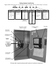
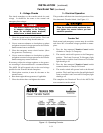
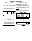
harness
plugs
S1 DIP
switch
S2 DIP
switch
(load d isconnect feature)
seepage5---1
Figure 4-2. Location of DIP switch.
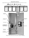
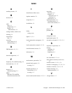
DIP
switch
S1
actuator
onoff
(8 on each DIP switch)
Figure 4-3. Setting DIP switch actuator.