


10
MODEL 1056DP SECTION 3.0
INSTALLATION AND WIRING
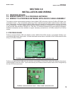
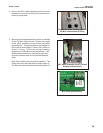
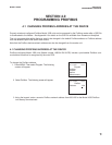
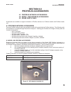
Ensure that the 10-lead ribbon cable is properly
connected from the Profibus board to the 10-pin
shrouded connector labeled “DIG I/O” on the main
printed circuit board (see photo).
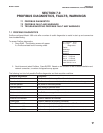
5.
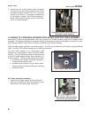
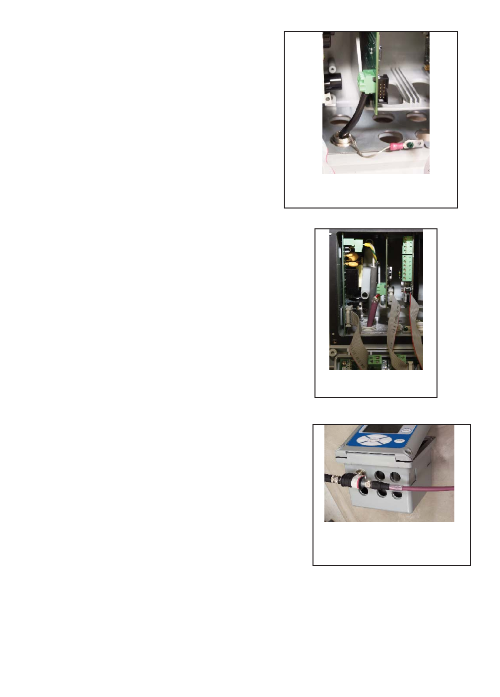
Connect the Model 1056 Profibus unit to a Profibus
network cable (purple) using standard Profibus
connectors and cable fittings. Once power is wired
to the unit (as shown in photo), the Profibus-
configured Model 1056 is ready for power up and
communication on a Profibus network.
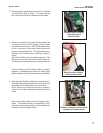
Complete M12 cable
assembly installation
Profibus M12 Cable assembly
attached to Profibus network
T-cable fitting
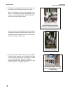
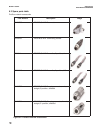
4. Slide the wired 4-lead terminal block onto the 4 pins
protruding from Profibus board on the left side.
Note: the Profibus cable must be directed down-
wards. The Profibus board can be partially or fully
removed to allow easy insertion of the 4-lead termi-
nal block onto the Profibus board.
Wired 4-lead terminal block
installed on Profibus DP board.