


8
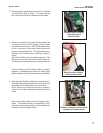
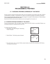
6. Ensure that the 10-lead ribbon cable is properly
connected from the Profibus board to the 10-pin
shrouded connector labeled “DIG I/O” on the main
printed circuit board. Once power is wired to the
unit (as shown in photo), the Profibus-configured
Model 1056 is ready for power up and communica-
tion on a Profibus network.
3.3 WIRING TO A PROFIBUS NETWORK WITH AN M12 ADAPTOR CABLE ASSEMBLY
Alternatively, Profibus-configured Model 1056 can be wired to a Profibus network using an M12 adaptor cable
assembly. The adaptor assembly kit accessory offered by Rosemount Analytical is designed to connect to a stan-
dard Profibus network T-cable which is directly connected to the Profibus network.
The M12 cable adaptor assembly is an ordering option. The kit is not provided with the Profibus-configured Model
1056. See Sec. 6.0 Profibus Accessories for ordering information.
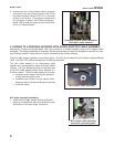
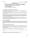
The M12 cable adaptor is an interconnect cable
between the communications board and the Profibus
network. The 5-pin female connector on the fitting end
of the M12 cable adaptor allows direct interface to a
Profibus network. The M12 cable adaptor kit includes:
a. threaded metal adaptor fitting with soldered
4-lead cable and ground wire
b. threaded metal nut and o-ring to secure metal
fitting and cable to enclosure through an opening
c. Instruction sheet
MODEL 1056DP SECTION 3.0
INSTALLATION AND WIRING
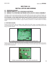
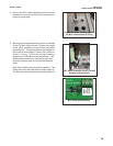
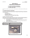
M12 cable assembly installation
1. Install the M12 cable adaptor through enclosure
opening on the leftmost side of the enclosure near-
est the front of the door hinge. See photo.
M12 adaptor cable assembly
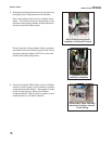
Complete Profibus board installation
with ribbon cable attached
M12 adaptor cable assembly
secured to grounding plate.