


5
SECTION 3.0
INSTALLATION AND WIRING
3.1 PROFIBUS BOARD
3.2 WIRING DIRECTLY TO A PROFIBUS NETWORK
3.3 WIRING TO A PROFIBUS NETWORK WITH AN M12 CABLE ASSEMBLY
MODEL 1056DP SECTION 3.0
INSTALLATION AND WIRING
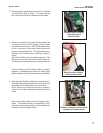
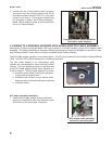
This section outlines recommended methods of wiring Model 1056 units which include a Profibus DP digital com-
munications board. The conventional method is to wire a standard purple Profibus cable directly to the instru-
ment. Alternatively, Profibus-configured Model 1056 units can be wired to a Profibus network using an M12 adap-
tor cable assembly. The M12 adaptor cable assembly offered by Rosemount Analytical is an ordering option and
is not provided with the Model 1056-DP unit. See Sec. 6.0 Profibus Accessories for parts ordering information.
Additional accessories are also available to support necessary connections to a Profibus network and Profibus
master.
3.1 PROFIBUS BOARD
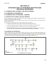
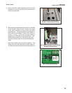
Profibus-configured Model 1056 units (Model number 1056-0X-2X-3X-DP) include a pre-installed Profibus com-
munications board and a ribbon cable. A 4-lead removable terminal block is installed on the Profibus board to allow
wiring to a Profibus network.
Profibus-configured Model 1056 units also include a pre-installed 10-lead ribbon cable that interfaces the commu-
nications board to the main PCB. Upon initial start-up, the Profibus communications board will be recognized by
the main PCB microprocessor.
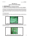
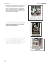
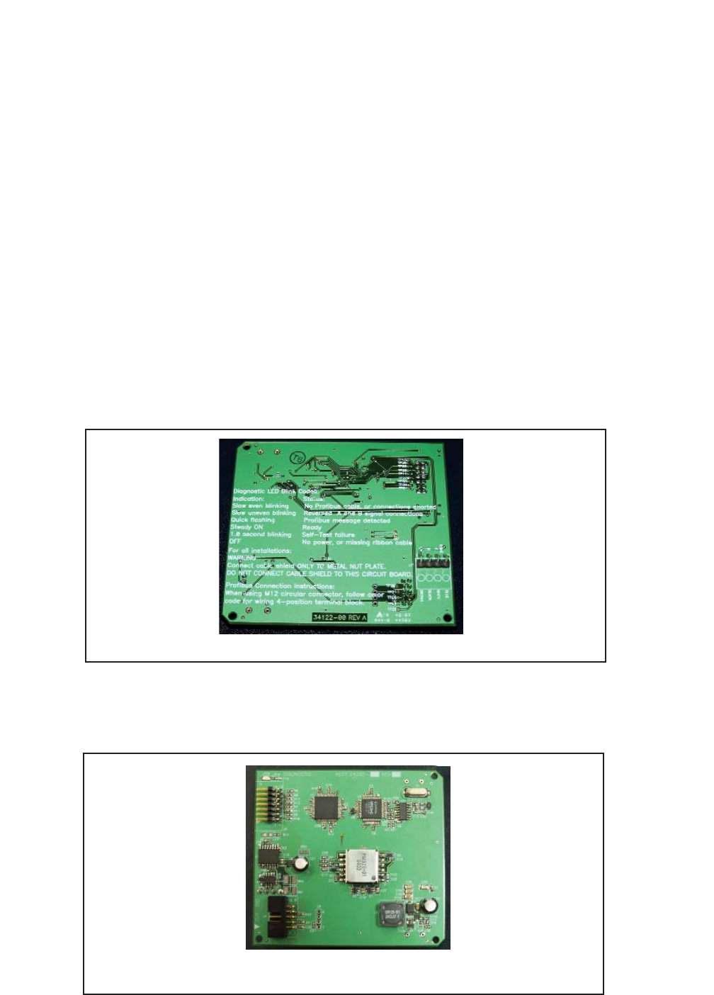
Profibus communications board – Profibus cable connection side
Profibus communications board – ribbon cable connection side