


7
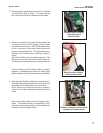
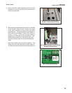
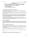
3. Remove the 4-lead terminal block which is installed
on the Profibus slide-in board. This photo shows
the 4-lead terminal block installed onto the board.
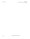
4. Wire the two leads of the purple Profibus cable (red
and green) to the A and B positions of the 4-lead
removable terminal block. A #0 Philips head screw
driver is required to open and close the terminal
posts on the terminal block. The lead positions are
labeled on the Profibus card (A and B) to assist in
wiring.
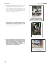
Note: that Profibus wiring is polarity-sensitive. The
Green color lead must be wired to lead position A.
The Red color lead must be wired to lead position B.
Caution: Make sure the Profibus cable is properly
prepared. Unshielded wire leads can lead to poor
signal integrity from the Profibus device to the Master
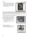
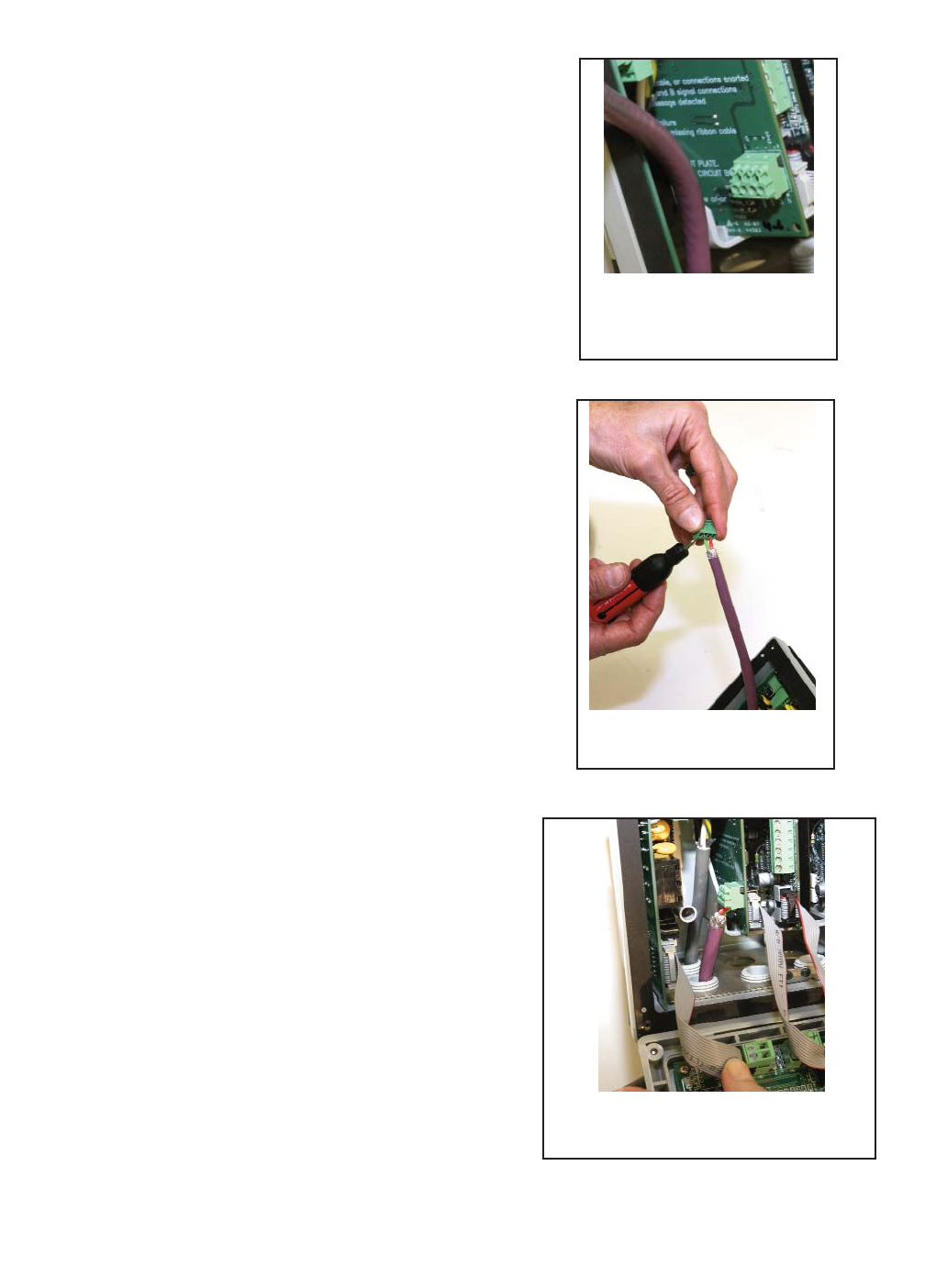
5. After wiring the Profibus cable to the terminal block,
slide the wired 4-lead terminal block onto the 4 pins
protruding from Profibus board on the left side.
Photo shows the 4-lead terminal block properly
wired to the Profibus board and installed onto the
board.
Note: the Profibus cable must be directed down-
wards. The Profibus board can be partially or fully
removed to allow easy insertion of the 4-lead termi-
nal block onto the Profibus board.
MODEL 1056DP SECTION 3.0
INSTALLATION AND WIRING
Profibus board showing
removable 4-lead
terminal block
Wiring Profibus cable to
4-lead terminal block
Profibus cable and terminal block
installed to Profibus board