Troubleshooting Guide 5 - 7
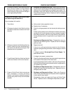
1a. Verify the actual inlet flow rate. Reduce flow rate if operating
above the inlet flow rate specified on the Dryer Specification La-
bel.
If the verified inlet flow rate is not exceeding the specified de-
sign flow rate, proceed to POSSIBLE CAUSE #1b.
1b. Allow the dryer to remain energized and operating in a fixed
cycle.
The High Humidity Alarm will de-energize (followed by the con-
trol system’s return to Energy Management System (EMS) Ac-
tive) AFTER the excessive moisture-load has been purged from
the desiccant beds.
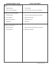
2. 1.SLOWLY rotate Purge Adjusting Valve until correct purge
pressure setting is noted on the Purge Pressure Indicator.
Note: The purge pressure setting can only be read and ad-
justed when the off-stream chamber has depressurized for re-
generation. When the off-stream chamber is pressurized the
Purge Pressure Indicator will read system pressure.
3. Shutdown and Depressurize Dryer. Refer to the Purge and
Outlet Check Valve Maintenance procedure which is applicable
to your specific dryer model. Disassemble, clean and inspect
the Purge and Outlet Check Valves. Replace all worn or dam-
aged components as noted.
High Humidity Warning
Note: A High Humidity Warning will ALWAYS
cause the control system to automatically shift
to fixed cycle operation.
1. Compu-Save Sensor has sensed a moisture
overload condition within a desiccant bed due
to the presence of one (or both) of the follow-
ing conditions:
1a. Inlet flow rate (SCFM) is above dryer’s de-
sign inlet flow rate, as specified on the Dryer
Specification Label located on the inside
cover of the dryer system control enclosure.
Excessive flow rates will result in excessive
moisture loading of the desiccant beds. This
overload condition would raise the Compu-
Save Sensor’s moisture related frequency
signal above the microcomputer’s compara-
tor set point range, and therefore, would be
interpreted as a High Humidity Warning.
1b. Gas has been allowed to flow through dryer
for an extended period of time with the dryer
control system de-energized. When the con-
trol system is de-energized, one chamber is
automatically placed on-stream and regen-
eration is not conducted.
Without regeneration, the desiccant beds will
eventually be overloaded with moisture.
When the power supply was re-energized,
the moisture-overload condition raised the
Compu-Save Sensor’s moisture related fre-
quency signal above the microcomputer’s
comparator set point range, and therefore,
would be interpreted as a High Humidity
Warning.
2. Purge Adjusting Valve is supplying excessive
purge gas to regenerating chamber as indi-
cated by the Purge Pressure Indicator
(gauge).
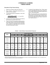
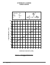
Note: If correct setting is unknown, refer to
the Calculation of Purge Pressure Setting in-
structions in Appendix A.
3. Purge or Outlet Check Valve seat is worn,
damaged, or fouled (allowing slight pressure
leakage to enter regenerating chamber).
PROBLEM/POSSIBLE CAUSE CHECKS AND REMEDY


