DISASSEMBLY/ASSEMBLY INSTRUCTIONS
ACTUATOR SUBASSEMBLY
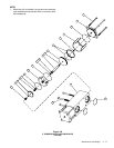
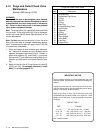
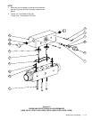
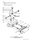
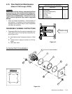
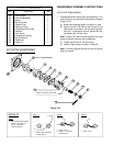
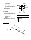
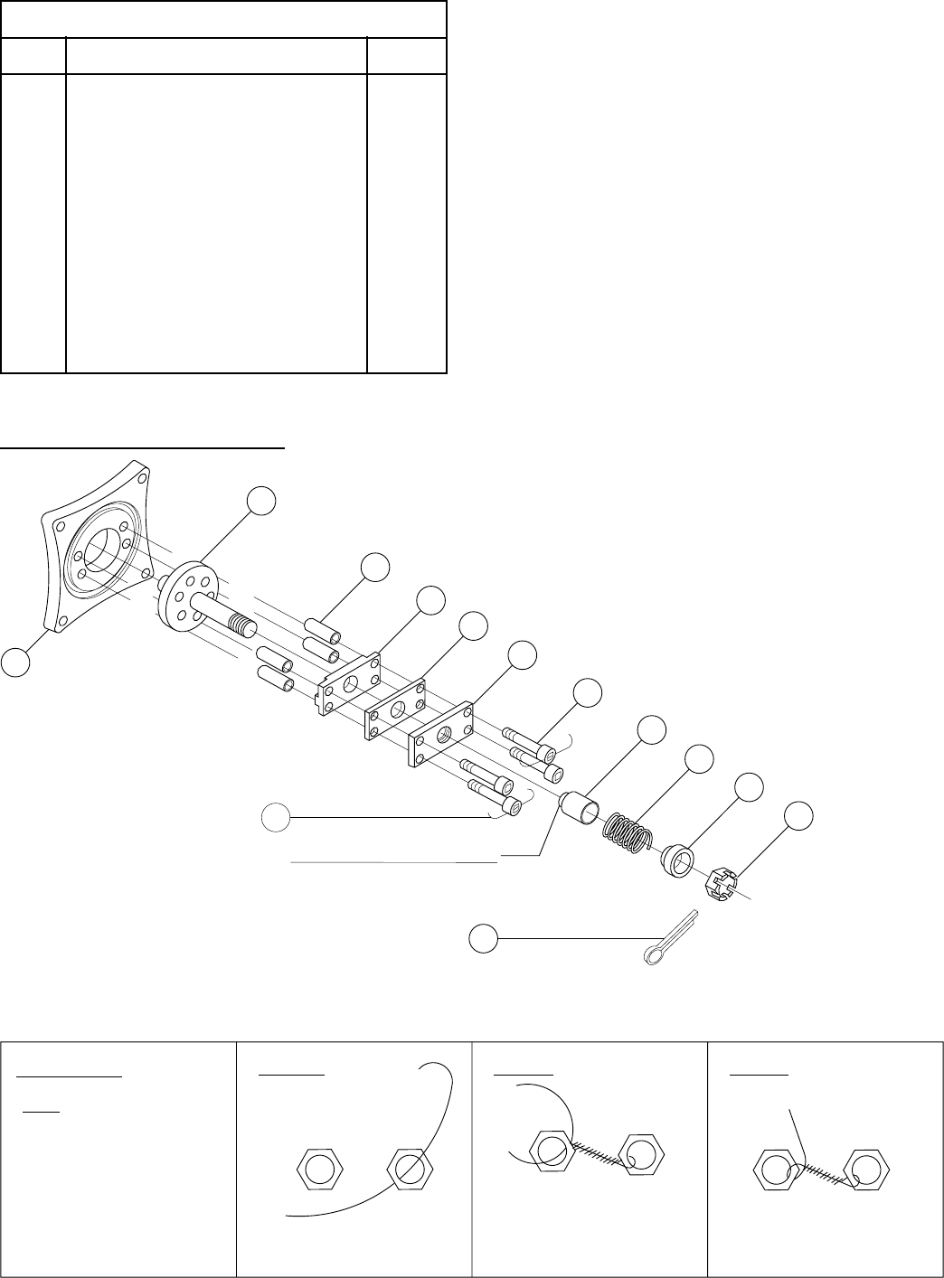
1. Disassemble/Build the actuator subassembly in the
order shown by the Actuator Subassembly Diagram
(Figure 4.15).
A) Secure the retaining plate in the jaws of a vise.
B) Apply Loctite™ RC-620 to the threads of the
shaft guide and thread it into the retaining plate.
Using a 1" combination wrench tighten with ap-
proximately 80-100 lbs. force.
Note: Loctite™ RC-620 must be applied to the shaft
guide to prevent loosening during operation.
C) Tighten cap screws to 4-5 lbs. torque.
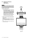
D) Lockwire cap screws as shown in Detail B.
Note: Correctly applied lockwire will tend to tighten
both cap screws.
ACTUATOR SUBASSEMBLY
Figure 4.15
2J
SHAFT SUBASSEMBLY
APPLY LOCTITE TO THDS
2K
2L
2M
2G
2F
2E
2D
2C
2B
2A
2H
2N
DETAIL 'B'
STEP '1'
1
STEP '2'
NOTE:
1.
A
B
STEP '3'
B
A
2
1.
2.
1.
21
AB
2
1
1.
WIRE SHOULD BE TWISTED
TIGHTLY AND WITHOUT
SLACK. USE WIRE
TWISTER PLIERS.
INSERT WIRE THROUGH
CONNECTOR '2'
TWIST 'A' & 'B'
INSERT 'B' THROUGH
CONNECTOR '1'
TWIST 'A' & 'B'
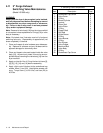
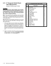
ACTUATOR SUBASSEMBLY
Item Description Total
2A Valve Flange 1
2B Shaft Subassembly 1
2C Spacer 4
2D Mounting Plate 1
2E Vibration Pad 1
2F Retaining Plate 1
2G Sockethead Cap Screw 4
2H Lockwire 1
2J Shaft Guide 1
2K Compression Spring 1
2L Spring Retainer 1
2M Slotted Nut 1
2N Cotter Pin 1


