


3 - 2 Operation
Do not start the dryer with compressed air flow through
the dryer. Close customer supplied dryer shut-off valves
before beginning start-up procedure.
1. Refer to the General Arrangement drawing as neces-
sary for component identification and location while
conducting start-up and operational procedures.
Note: If your dryer cannot be started, or fails to start
due to special installation or other problems, contact
your local Deltech Sales Representative for assis-
tance.
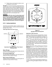
2. Remove the Pilot Gas Filter Bowl. Verify that the pi-
lot gas filter cartridge is installed. Replace Filter
Bowl ensuring that O-ring is properly seated. Close
the filter bowl bleed valve.
3. All Prefilter and Afterfilter Assemblies are shipped
WITH filter cartridges installed. Verify that prefilter
and afterfilter cartridges are installed. Prefilter and
Afterfilter cartridges are NOT interchangeable and
must be installed in their respective assemblies
ONLY. The proper filter cartridge part number is
listed on each Prefilter and Afterfilter Assembly.
4. Replace and tighten filter assembly bowls. Ensure
that O-rings are properly seated.
5. Close any manual vent or drain valves installed in pre-
filter and afterfilter assemblies.
6. If the prefilter assembly was factory equipped with an
automatic drain valve, inspect for, and remove pipe
plug or cap which may have been installed in drain
port for shipping purposes. Ensure isolation ball valve
to automatic drain valve is open.
7. Ensure that all associated pipe and tubing connec-
tions, flanges, unions, plugs, mounting bolts, pipe
hangers, etc., have been checked tight and/or prop-
erly secured.
IMPORTANT: It is recommended that the System's
process gas output not be consumed or used at the
intended points of use until the Start-Up and any re-
lated adjustments have been completed, and the
system is producing process gas of the required
quality. The quality of the process gas should be veri-
fied through test and analysis when a specific quality
process gas is required.
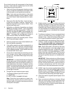
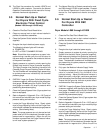
8. Energize the dryer’s electrical power supply.
The following indicator lights will illuminate:
a) POWER ON
b) LEFT or RIGHT CHAMBER DRYING
Note: Should the dryer experience a power inter-
ruption during a normal cycle, the unit will return to
the same status of operation that existed at the time
of the power interruption.
9. Supply pressure to system by slowly opening the
System Inlet Isolation Valve (customer supplied).
The Right Chamber Inlet Switching Valve and Left
Chamber Purge Exhaust Switching Valve will close.
The Left Chamber will immediately begin pressurizing
to system pressure as indicated by the chamber
pressure gauge.
10. The Moisture Indicator's (if dryer so-equipped) bleed
valve is installed directly into the back of the
indicator's body. Close the Indicator's Bleed Valve.
FULLY open the Moisture Indicator Supply Valve.
11. Soap bubble test all external piping, fittings, and con-
nections. Locate and repair all noted points of leak-
age. Do not soap bubble test components lo-
cated inside dryer control system's enclosure.
Note: Small leaks noted in inlet piping to the dryer
will not affect operation, other than a slight loss of
pressure supplied to the dryer. HOWEVER, any gas
leaks, (no matter how small), detected at, or down-
stream of the dryer outlet MUST BE FIXED to ensure
that the dryer will provide a continuous supply of pro-
cess gas at specified dew point, to intended points-
of-use.
IMPORTANT: Water molecules can diffuse through
a pinhole-size leak even though pressure inside the
piping is several hundred PSIG. It is not uncommon
to have a minute pinhole leak in a gas line cause an
increase in dew point from -40°F to -10°F at a dis-
tance of forty or more feet downstream of the leak.
12. SLOWLY open the customer-supplied System Outlet
Isolation Valve, while monitoring the Outlet Pressure
Gauge (if dryer so-equipped). DO NOT permit the
Dryer's Outlet Pressure Gauge to exceed a 5% drop
in pressure while pressurizing downstream piping.
13. Close the customer-supplied System Bypass Valve
(if installed).
14. Open and adjust the Moisture Indicator’s Bleed
Valve until a very slight, continuous gas bleed is felt
exhausting from the bleed valve’s exhaust port. En-
sure that the granular indicator crystals remain mo-
tionless after final adjustment.