8
Curtis enAble
®
40-Series Manual, Rev. B
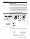
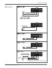
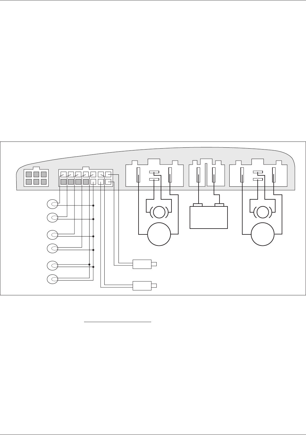
Fig. 5 Basic wiring diagram, Curtis 1740 powerbase.
2 — INSTALLATION & WIRING
POWERBASE WIRING
Wiring for the 1740 powerbase is shown in Figure 5. The connections to the
14-pin connector are optional, depending on the level of functionality desired.
For use with the simplest handcontrol (the basic drive-only version), no logic
connections are required; for use with the full featured handcontrol (drive with
lights and seat actuators), all the connections shown in Figure 5 are required.
Additional features can be added to the system by wiring additional components
to the Multi-Function pins (4–7); see Figure 6.
The motor and battery connector housings have been specifically designed
for the enAble 40 system and must be purchased directly from your Curtis
dealer or sales representative. The electrical connectors are standard AMP parts.
Curtis also provides a kit with all the parts required to connect the high power
wiring to the powerbase. See Appendix C for part numbers.
14-pin logic connector
The mating connector is 14-pin Molex Mini-Fit Junior, p/n 39-01-2140. You
should use the matching Molex pins, p/n 44476-3112, which are suitable for
high current, and 18–24 AWG wire. The pin-out is as follows:
Pin 1 Seat Motor 1+ Pin 8 Seat Motor 1-
Pin 2 Seat Motor 2+ Pin 9 Seat Motor 2-
Pin 3 B+ Pin 10 Running Lights -
Pin 4 B- Pin 11 Front Right Turn -
Pin 5 Multi-Function Input 1 Pin 12 Front Left Turn -
Pin 6 Multi-Function Input 2 Pin 13 Rear Right Turn -
Pin 7 Multi-Function Input 3 Pin 14 Rear Left Turn -
BATT
M2
M1
+–
4
1 1
8
M2M1
Actuator 1
Actuator 2
Rear
L Turn
Rear R Turn
Front L Turn
Front R Turn
Running Lights


