Installation Instructions CM2C40
7
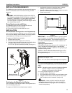
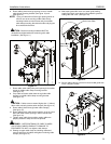
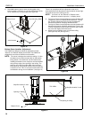
15. Align studs in faceplate with appropriate holes in faceplate
mounting bracket and hang faceplate on bracket with studs.
16. Secure faceplate to faceplate mounting bracket using two
locknuts. (See figure 7)
Figure 7
Cable Installation and Routing
The CM2C40 has an integrated cable management system that
allows cables to be automatically "fed out" as the lift raises, and
"reeled in" as the lift lowers while maintaining constant cable
tension.
NOTE: Some components have been removed for clarity in
the artwork associated with this procedure.
IMPORTANT ! : The CM2C40C40 requires minimum cable
lengths of 8 feet from display through lower mount.
To install cables:
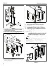
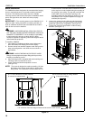
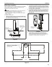
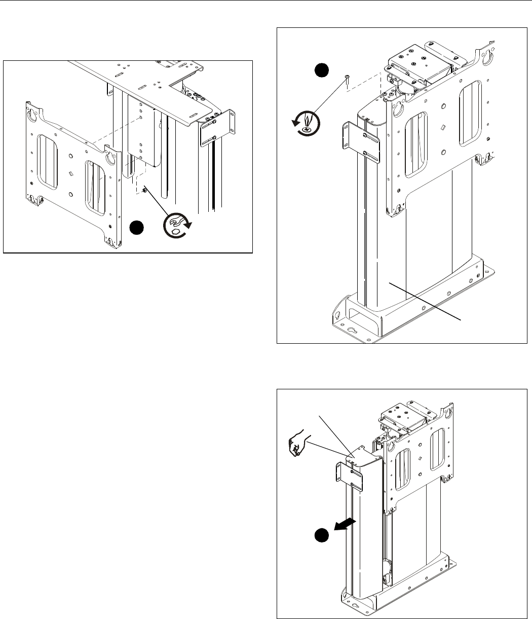
1. Remove two screws securing cable guide side cover.
2. Set screws aside for reuse. (See figure 8)
Figure 8
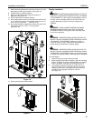
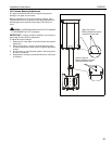
3. Slide cable guide side cover away from mount and carefully
set aside.
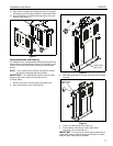
Figure 9
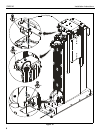
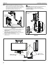
4. Loosen six cable clamps. (See figure 10)
5. Route cable(s) down through upper cable clamp.
(See figure 10) and (See figure 11)
IMPORTANT ! : Leave enough cable length available above
upper cable clamp to allow the routing and tie-down of cables
between upper cable clamp and display.
16
x2
x2
1
Cable Guide
Side Cover
Cable Guide
Side Cover
3


