


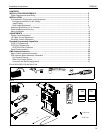

Installation Instructions CM2C40
11
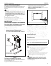
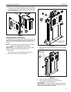
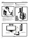
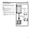
7. While maintaining dimensions referenced in figure 15, mark
base plate mounting hole locations. (See figure 16)
8. Drill pilot holes at marked locations.
9. Mark four side bracket mounting hole locations if
applicable. (See figure 16)
10. Drill four pilot holes at marked locations.
11. Secure base plate to structure using either two (wall mount)
or six (ceiling mount) 5/16" flat washers and two or six six
5/16" x 2 1/2" lag screws. (See figure 16)
12. Secure side brackets, if applicable, to studs using four 5/16"
flat washers and four 5/16" x 2 1/2" lag screws.
(See figure 16)
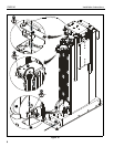
Figure 16
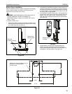
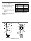
13. Connect mount power cord to outlet.
Figure 17
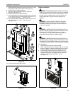
Display Installation
WARNING: EXCEEDING MAXIMUM WEIGHT CAPACITY
CAN LEAD TO SERIOUS PERSONAL INJURY OR AMAGE
TO EQUIPMENT! It is the installers responsability to ensure
the total amount of weight placed on the mount does not
exceed 190lbs (86.18 kg) the maximum capaity of the
CM2C40.
WARNING: PINCH HAZARD! FINGERS OR HANDS
BETWEEN MOVING PARTS CAN LEAD TO SEVERE
PERSONAL INJURY! Keep fingers and hands away from
mount when operating.
WARNING: IMPROPER INSTALLATION CAN LEAD TO
MOUNT FALLING CAUSING SEVERE PERSONAL INJURY
OR DAMAGE TO EQUIPMENT. Displays can weigh in
excess of 40 lbs (18.1kg). ALWAYS use two people and
proper lifting techniques when installing display.
WARNING: IMPROPER INSTALLATION CAN LEAD TO
MOUNT FALLING CAUSING SEVERE PERSONAL INJURY
OR DAMAGE TO EQUIPMENT. Make sure mounting buttons
on display are properly seated in mounting holes in faceplate.
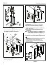
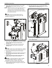
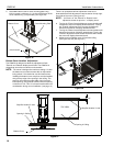
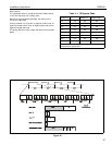
To install display:
1. Lower lift using the remote control provided.
2. While supporting both sides of display, align four mounting
buttons on display or interface bracket with four mounting
holes in faceplate. (See figure 18) and (See figure 19)
3. Lower display into place listening for audible "click" to
ensure recessed area of mounting buttons are properly
seated in lower area of mounting holes and "click lock"
mechanism has engaged. (See figure 18) and
(See figure 19)
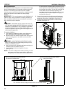
Figure 18:
12
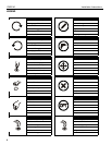
10
X6
X4
8
13
11
X4
9
12
1
1
3
2