


CM2C40 Installation Instructions
12
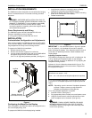
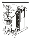
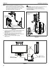
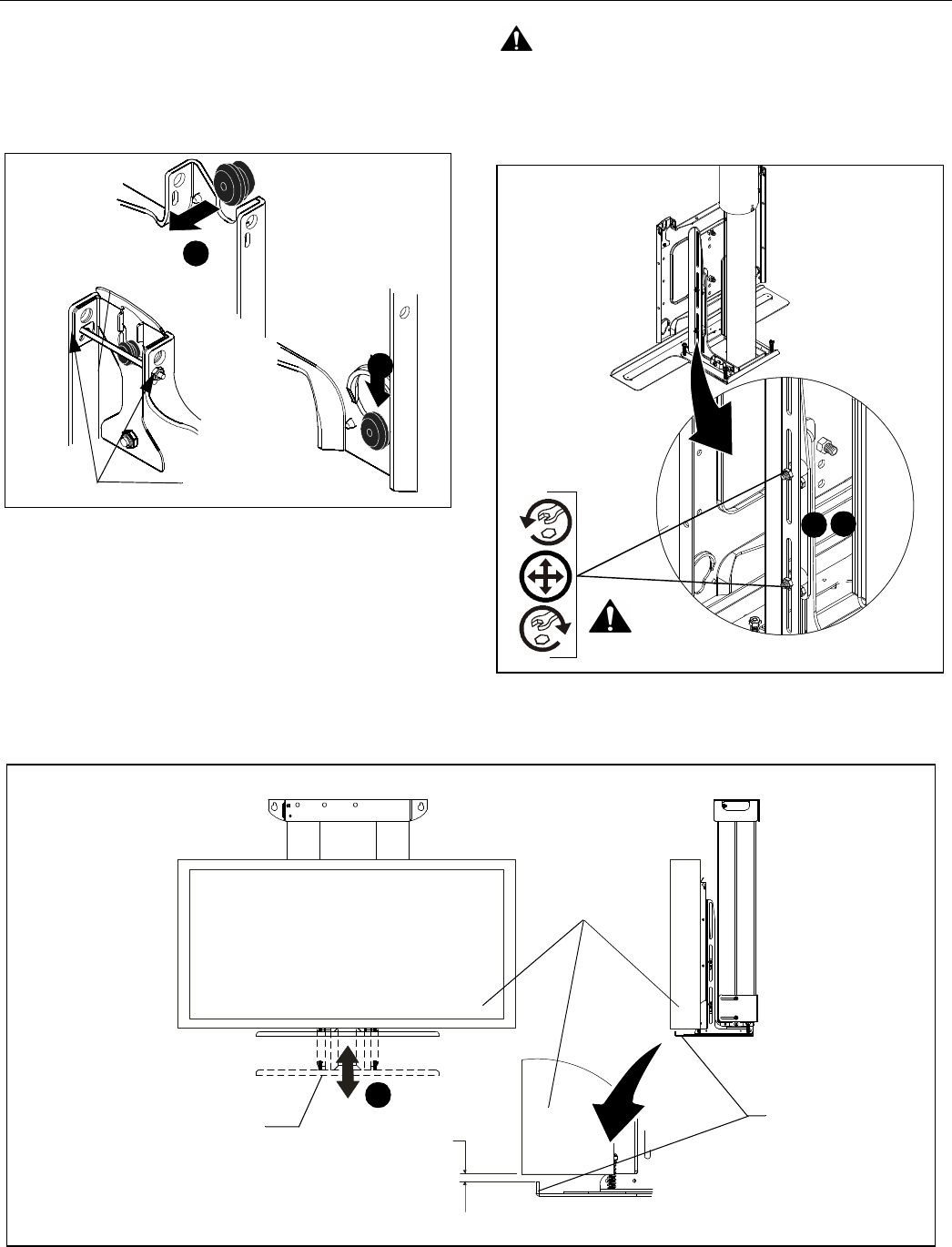
NOTE: Holes are provided in the faceplate for use with a
padlock or similar locking device, if desired. In addition,
the pin and nut may be removed from the upper holes
and moved to the lower holes for use as a more
permanent locking device. (See figure 19)
Figure 19
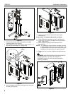
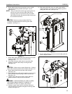
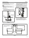
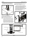
4. Loosen four nuts securing right and left hand bottom cover
adjustment brackets to faceplate mounting bracket.
(See figure 20)
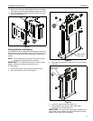
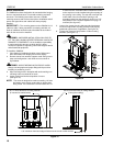
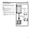
5. Slide bottom cover adjustment brackets upward or
downward until lip on bracket is positioned 1/4" below the
bottom of display. (See figure 21)
6. Tighten four nuts to secure bracket in position.
(See figure 20)
WARNING: IMPROPER INSTALLATION CAN LEAD TO
SEVERE PERSONAL INJURY OR DAMAGE TO
EQUIPMENT! Make sure all four nuts are tight before
continuing installation!
Figure 20
2
1
Remove pin
and nuts and
move to lower holes.
A padlock or bolt may
be placed through latch
holes
3
X4
Display removed
for clarity
5
Figure 21
1/4" minimum
Display
Bottom Cover
Mounting Bracket
Bottom Cover
Mounting Bracket
4