


Aruba Mobility Controller Configuration Guide
VIEW Certified
Page 2
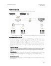
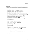
Network Topology
The following topology was tested during VIEW Certification testing.
Deployment Description
It is required that voice users be placed on a separate VLAN (e.g., VLAN 10) and data users
on a separate VLAN (e.g., VLAN 25). The voice and data VLANs reside on the Aruba mobility
controller and not on the access points (APs). The user traffic is tunneled back to the Aruba
controller for processing. The edge network thus does not have to be modified to
accommodate the WiFi clients and the VoWiFi network. Map each VLAN to a unique subnet.
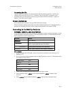
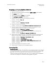
The mobility controller (switch) IP address needs to be set via the loopback interface setting.
The Controller’s loopback address must be a routable address so that the APs can reach this
address.
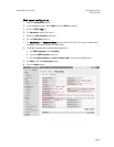
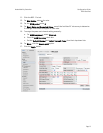
Interface setting
Identify the mobility controller port that serves as the uplink port for the data VLAN. The port
used in this example is Fast Ethernet 1/0 and is a trunk port with both the voice and data
VLAN.
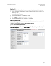
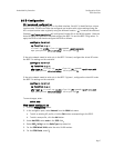
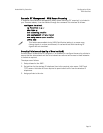
Default route
The L3 switch connected to the Aruba controller serves as the default gateway for all the WiFi
clients. Configure the default route to the next-hop gateway connected to the mobility
controller.
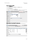
Physical interface
All interfaces that connect to the core networks, routers, servers and gateways need to be set
as trusted ports.