


Performance characteristics (continued)
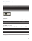
Display system
Display 6.3-inch (161 mm) diagonal color TFT LCD
Throughput of scope channels Up to 100,000 waveforms/sec in real-time mode
Resolution XGA – 768 vertical by 1024 horizontal points (screen area);
640 vertical by 1000 horizontal points (waveform area)
256 levels of intensity scale
Controls Waveform intensity on front panel. Vectors on/off; infinite persistence on/off,
8 x 10 grid with intensity control
Built-in help system Key-specific help displayed by pressing and holding key or softkey of interest.
Language support for 11 languages including English, German, French, Russian, Japanese,
Traditional Chinese, Simplified Chinese, Korean, Spanish, Portuguese and Italian.
Real-time clock Time and date (user adjustable)
Measurement features
Automatic measurements Measurements are continuously updated. Cursors track last selected measurement.
Up to four measurements can be displayed on screen at any one time.
Voltage (scope channels only) Peak-to-peak, maximum, minimum, average, amplitude, top, base, overshoot, preshoot, RMS,
standard deviation (AC RMS), Ratio (dB)
Time Frequency, period, + width, – width and duty cycle on any channel.
Rise time, fall time, X at max Y (time at max volts), X at min Y (time at min volts), delay, and
phase on scope channels only.
Counter Built-in 5-digit frequency counter on any channel. Counts up to the scope’s bandwidth (1 GHz
max). The counter resolution can be increased to 8 digits with an external 10-MHz reference.
Threshold definition Variable by percent and absolute value; 10%, 50%, 90% default for time measurements
Cursors Manually or automatically placed readout of horizontal (X, ∆X, 1/∆X) and vertical (Y, ∆Y).
Tracking Cursors provides an additional mode for cursor positioning beyond the current
manual method. When cursor tracking is enabled, changing a cursor’s x-axis position
results in the y-axis cursor tracking the corresponding y-axis (voltage, current, etc.) value.
Additionally logic or scope channels can be displayed as binary or hex values.
Waveform math f (g(t))
g(t): { 1, 2, 3, 4, 1-2, 1+2, 1x2, 3-4, 3+4, 3x4}
f(t): { 1-2, 1+2, 1x2, 3-4, 3+4, 3x4, FFT(g(t)), differentiate d/dt g(t), integrate ∫ g(t) dt, square
root √g(t) } Where 1,2,3,4 represent analog input channels 1, 2, 3, and 4
Note: Channels 3 and 4 only available on MSO/DSO6xx4A models
Measurement statistics Statistical data for enabled measurements such as mean, min, max, standard deviation
and count
22