


Performance characteristics (continued)
Vertical system: scope channels (continued)
ESD tolerance ±2 kV
Noise, RMS, input shorted MSO/DSO601xA: 0.50% FS or 250 µV, whichever is greater
MSO/DSO603xA: 0.50% FS or 300 µV, whichever is greater
MSO/DSO605xA: 0.50% FS or 360 µV, whichever is greater
MSO/DSO610xA: 0.65% FS or 360 µV, whichever is greater
DC vertical gain accuracy*
1
±2.0% full scale
DC vertical offset accuracy ≤200 mV/div: ±0.1 div ±2.0 mV ±0.5% offset value;
>200 mV/div: ±0.1 div ±2.0 mV ±1.5% offset value
Single cursor accuracy
1
±{DC vertical gain accuracy + DC vertical offset accuracy + 0.2% full scale (~1/2 LSB)}
Example: for 50 mV signal, scope set to 10 mV/div (80 mV full scale), 5 mV offset,
accuracy = ±{2.0% (80 mV) + 0.1 (10 mV) + 2.0 mV + 0.5% (5 mV) + 0.2% (80 mV)} =
± 4.785 mV
Dual cursor accuracy*
1
±{DC vertical gain accuracy + 0.4% full scale (~1 LSB)}
Example: for 50 mV signal, scope set to 10 mV/div (80 mV full scale), 5 mV offset,
accuracy = ±{2.0% (80 mV) + 0.4% (80 mV)} = ±1.92 mV
* Denotes warranted specifications, all others are typical. Specifications are valid after a 30-minute warm-up period and ±10 °C from firmware calibration temperature.
1 1 mV/div is a magnification of 2 mV/div setting for 100 MHz models and 2 mV/div is a magnification of 4 mV/div setting for 300 MHz to 1 GHz models. For vertical accuracy
calculations, use full scale of 16 mV for 1 mV/div sensitivity setting and 32 mV for 2 mV/div sensitivity setting.
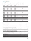
Vertical system: digital channels (MSO6000A or MSO-upgraded DSO6000A only)
Number of channels 16 logic timing channels – labeled D15 - D0
Threshold groupings Pod 1: D7 - D0
Pod 2: D15 - D8
Threshold selections TTL, CMOS, ECL and user-definable (selectable by pod)
User-defined threshold range ±8.0 V in 10 mV increments
Maximum input voltage ±40 V peak CAT I; transient overvoltage 800 Vpk
Threshold accuracy* ±(100 mV + 3% of threshold setting)
Input dynamic range ±10 V about threshold
Minimum input voltage swing 500 mV peak-to-peak
Input capacitance ~8 pF
Input resistance 100 kΩ ±2% at probe tip
Channel-to-channel skew 2 ns typical, 3 ns maximum
* Denotes warranted specifications, all others are typical. Specifications are valid after a 30-minute warm-up period and ±10 °C from firmware calibration temperature.
18