


TIC-LF654L
3
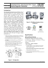
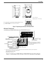
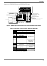
Model LF620 and LF622 converters
Input signals
Analog signal — the voltage signal from detector,
proportional to process flow rate (for LF622
separate type converter).
Digital input DI
Signal type: 20 to 30Vdc voltage signal
Input resistance: 2.7k
Number of inputs: one point
Note: DI cannot be used with the Modbus communication.
DI function — One of the following functions can
be assigned to the DI signal.
Range switching — Selects either the higher or
lower range in the unidirectional or bidirectional
2-range setting.
Totalizer control — ‘Starts and stops’ or ‘Rest and
start’ the built-in totalizer.
Fixed-value outputs —Outputs fixed-values for
current and pulse outputs for loop check.
Zero adjustment — Executes zero adjustment
(on-stream at zero flow rate).
Output signals
Current output:
4–20mAdc (load resistance 0 to 750)
Note: The current output cannot be used with the
PROFIBUS-PA communication.
(Refer table 6 for details)
Digital outputs — Two points are available as
follows.
Digital output DO1:
Output type: Transistor open collector
Number of outputs: One point
Output capacity: 30Vdc, 200mA maximum
Note: DO1 cannot be used if Modbus
communication connection is 3 lines.
(Refer table 6 for details)
Digital output DO2 :
Output type:
Solid-state relay output (non polarity)
Number of outputs: One point
Output capacity: 150Vdc, 150mA maximum or
150Vac (peak to peak), 100mA maximum
Note: DO2 cannot be used with the Modbus
communication. (Refer table 6 for details)
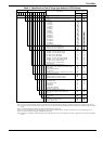
DO1 and DO2 functions — One of the following
functions can be assigned to DO1 and/or DO2 .
• Pulse output (available only for DO1, DO2)
Pulse rate: MAX 10kHz (10000pps)(DO1)
MAX 100Hz (100pps)(DO2)
(Over 1kpps, auto-setting)
Pulse width: 0.5 to 500ms (but less than half of
the period for 100% flow rate)
Note: The same and simultaneous pulse is not available
between DO1 and DO2.)
• Multi-range selection outputs (Note 1)
• High, High high, Low, and/or Low low alarm
outputs (Note 2)
• Empty pipe alarm output (Note 2)
• Preset count output
• Converter failure alarm output
Note 1: Two outputs (DO1 and DO2) are needed for 4-range
switching and forward/reverse 2-range switching.
Note 2: Normal Open (default set) or Normal Close is selected
for alarm outputs when programming.
When power failure occurs, unit will be fault to Normal
Open.
Communications output:
• HART (std.) — Digital signal is superimposed on
4–20mAdc current signal as follows:
Conforms to HART protocol
Load resistance: 240 to 750
Load capacitance: 0.25µF maximum
Load inductance: 4mH maximum
• PROFIBUS (opt.)
Protocol: PROFIBUS-PA
Baud rate: 31.25kbps
Bus voltage: 9-30VDC
Consumption electric current of bus: less than 16mA
Manufacture Ident-No.: 093B
HEX
Standard Ident-No.: 9740
HEX
Slave address: 0-126 (Default address is 126)
Profile: Profile Ver.3.01 for Process Control
Devices
Function blocks: AI(Flow) 1 , Totalizer 1
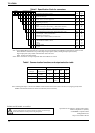
• MODBUS (opt.)
Physical layer : RS485
Protocol : Modbus
Mode : RTU
Baudrate : 4800, 9600, 19200bps
Data length : 8bit
Parity bit : None, Odd, Even
Stop bit : 1bit, 2bit
Error check : CRC-16
Max. station number : 32(with Master device)
Max. cable length : 1.2km (Note)
Note: This length is specification of 3 line
connection.