


TIC-LF654L
10
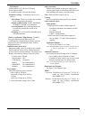
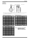
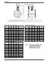
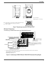
● Separate type LF650/LF622 flowmeter and LF654/LF622F flowmeter
G
roun
di
ng w
ith
100
or
l
ess
ground resistance
I
ns
t
rumen
t
pane
l
:
O
r
d
ere
d
separa
t
e
l
y
I/O cable
Grounding with 100 or less
ground resistance
wire 5.5mm
2
or more
Current output (4 20mAdc)
o
r PR
O
FIB
US
P
ower supp
l
y
Power cable
Di
g
it
a
l
i
npu
t
(20 30Vdc)
Si
gna
l
common
f
or
DI
an
d
DO
Digital output 1
Di
g
it
a
l
ou
t
pu
t
2
Grounding with 100 or less
ground resistance
or Modbus
Signal cable
(2-wire shielded hard-rubber sheathed cable)
Connected detector
Excitation cable
(3-wire shielded hard-rubber cable)
Thick walled steel conduit
Power switch
(External double-pole power switch)
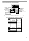
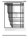
Figure 9. Separate type LF650/LF622 and LF654/LF622F flowmeters wiring Diagram
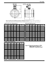
Table 1. LF620, LF620F, LF622 and LF622F Converters Signal Table
Symbol Description Cable
L1 ( )
Power supply Power cable (CVV)
L2 ( )
GND Ground (for arrester)
FG Frame groun
d
DI Digital Input (20 30Vdc)
I/O cable (CVV-S)
DO1 Digital Output 1
DO2 Digital Output 2
COM Signal Common for DI, DO1, DO2
Current Output (4 20mAdc)
or PROFIBUS
Shielded cable for
PROFIBUS-PA
X
Excitation cable
(for LF622,LF622F only)
Y Excitation Output
E
A
Signal cable
(for LF622,LF622F only)
B Signal Input
G
T+ Modbus(+)
Twisted-pair polyethylene
insulated vinyl sheath cable
(JKEV,AWG24(0.2mm
2
))
T- Modbus(-)
TG Modbus(GND)
Note: Symbol of the terminal is changed as follows for Modbus.
DO2 → T+, DI → T-, COM → TG