


A-6
Appendix Model 3000PA
Teledyne Analytical Instruments
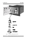
RESTRICTOR KIT
The current revision of the 3000 series analyzers are supplied with a kit
containing two restrictors and a union which are user installed. These parts
supplied to give the end user more flexibility when installing the analyzer. The
restrictor kit is suitable for high and low positive pressure applications as well as
vacuum service ( atmospheric pressure sample) applications ( see manual for
installation instructions). The standard restrictor ( BLUE DOT ) is recommended
for pressures between 5 PSIG and 50 PSIG. For positive low pressure
application ( 5 psig or less ) the un-marked restrictor is better suited . For
none pressurized sample applications the marked restrictor should be used and
configured for vacuum service. Note: for extremely low positive pressure
applications ( less then 2 psig) the vacuum service configuration should provide
higher performance ( higher flow rates). For vacuum service the end user must
supply a vacuum pump and a by-pass valve for the pump. A vacuum level of 5 -
10 inches of mercury should provide the optimum flow rate. CAUTION: flow
restrictors have very small orifices and may be plugged by small
particles ( .005” dia or larger) A sample filter must be included in the
sample line prior to the restrictor! ( a 60 micron filter is recommended)
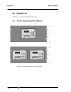
3000PA EXAMPLES:
Example 1, with a incoming pressure of 10 psig the std restrictor (blue
dot) will provide a flow rate of .76 SLPM. Up-stream of the restrictor the
sample line pressure will be 10 psig, while down stream ( including the cell) the
pressure will be at atmospheric pressure.( analyzer vented to atmospheric
pressure) Note, all other pressure drops in the sample path are insignificant at
these flow rates. This insures that the cell operates at atmospheric pressure. At
very high flow rates ( off scale of flow-meter), pressure drops other than the
restriction device could become significant , and result in pressurizing the cell.
Example 2, A 3000PA is configured for vacuum service as follows. The
un-marked restrictor is placed in the sample vent port. The down stream end of
the restrictor is then connected to a vacuum pump and by-pass valve. The by-
pass valve is adjusted to provide a flow rate of 1 SLPM. The sample pressure
between the pump and the restrictor will be approximately -7 inches of mercury,
while the pressure in the balance of the sample system including the cell will be
approximately at atmospheric pressure. ( provided the sample flow into the
analyzer is not blocked.)
BY-PASS:
To improve the system response, a by-pass can be added to increase
the sample flow rate to the analyzer by a factor of ten. A by-pass provides a
sample flow path around the analyzer of 2 - 18 SCFH. typically.
CALIBRATION GAS:
3000 series analyzer requirements for units with Auto-Cal options. The