


3 Installation Model 3000PA
3-4
Teledyne Analytical Instruments
The unit is manufactured with
1
/4 inch tube fittings. Six millimeter
adapters are supplied for metric system installations. For a safe connection:
1. Insert the tube into the tube fitting, and finger-tighten the nut until
the tubing cannot be rotated freely, by hand, in the fitting. (This
may require an additional
1
/8 turn beyond finger-tight.)
2. Hold the fitting body steady with a backup wrench, and with
another wrench rotate the nut another 1
1
/4 turns.
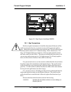
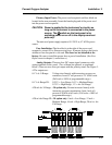
SAMPLE IN: In the standard model, gas connections are made at the
SAMPLE IN and EXHAUST OUT connections. Calibration gases must be
Tee'd into the Sample inlet with appropriate valves.
Ensure that the gas pressure is reasonably regulated. Pressures between
3 and 40 psig are acceptable as long as the pressure, once established, will
keep the front panel flowmeter reading in an acceptable range (0.1 to 2.4
SLPM). Exact figures will depend on your process.
If greater flow is required for improved response time, install a bypass
in the sampling system upstream of the analyzer input.
Note: If the unit is for vacuum service, the above numbers apply
instead to the vacuum at the EXHAUST OUT connector, de-
scribed below, with minus signs before the pressure readings.
EXHAUST OUT: Exhaust connections must be consistent with the
hazard level of the constituent gases. Check Local, State, and Federal laws,
and ensure that the exhaust stream vents to an appropriately controlled area if
required.
Note: If the unit is for vacuum service, see
Sample In
, above, for gas
pressure/flow considerations.
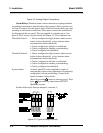
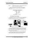
ZERO IN and SPAN IN (Optional): These are additional input ports
for span gas and zero gas. There are electrically operated valves inside for
automatic switching between sample and calibration gases. These valves are
under control of the 3000P Electronics. They can be externally controlled
only indirectly through the Remote Cal Inputs, described below.
Pressure, flow, and safety considerations are the same as prescribed for
the SAMPLE IN inlet, above.
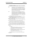
3.3.2 Electrical Connections
For safe connections, ensure that no uninsulated wire extends outside of
the connectors they are attached to. Stripped wire ends must insert com-
pletely into terminal blocks. No uninsulated wiring should be able to come in
contact with fingers, tools or clothing during normal operation.