


Percent Oxygen Analyzer Installation 3
3-5Teledyne Analytical Instruments
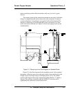
Primary Input Power: The power cord receptacle and fuse block are
located in the same assembly. Insert the female plug end of the power cord
into the power cord receptacle.
CAUTION: Power is applied to the instrument's circuitry as
long as the instrument is connected to the power
source. The switch on the front panel is for
switching power on or off to the displays and out-
puts only.
The universal power supply requires a 85–250 V ac, 47-63 Hz power
source.
Fuse Installation: The fuse block, at the right of the power cord
receptacle, accepts US or European size fuses. A jumper replaces the fuse in
whichever fuse receptacle is not used. The fuses are not installed at the
factory. Be sure to install the proper fuse as part of installation. (See Fuse
Replacement in chapter 5, maintenance.)
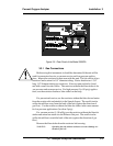
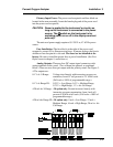
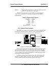
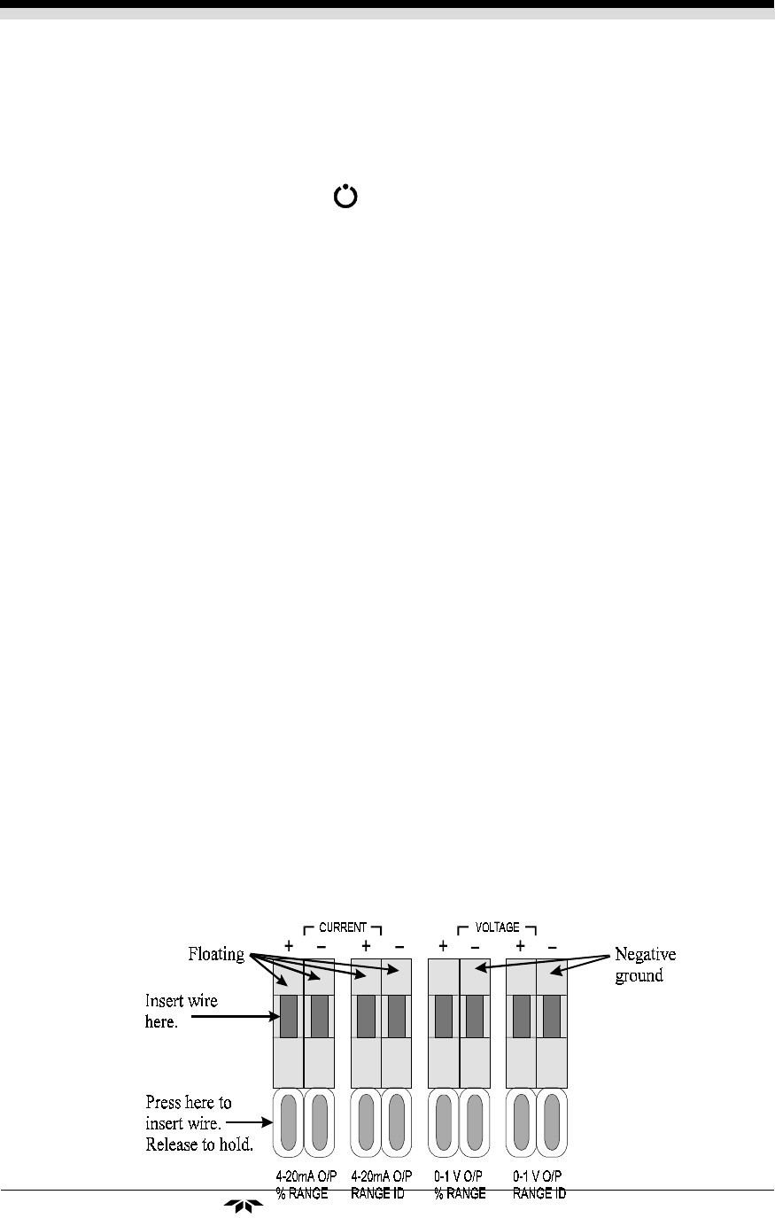
Analog Outputs: There are four DC output signal connectors with
spring terminals on the panel. (Two of them are optional, as explained
below.) There are two wires per output with the polarity noted. See Figure 3-
4. The outputs are:
0-1 V dc % Range: Voltage rises linearly with increasing oxygen con-
centration, from 0 V at 0 percent to 1 V at full scale.
(Full scale = 100% of programmable range.)
0-1 V dc Range ID: 0.25 V = Low Range, 0.5 V = Medium Range,
0.75 V = High Range, 1 V = Air Cal Range.
4-20 mA dc % Range: –M option only. Current increases linearly with
increasing oxygen concentration, from 4 mA at 0
percent to 20 mA at full scale. (Full scale = 100% of
programmable range.)
4-20 mA dc Range ID: –M option only. 8 mA = Low Range, 12 mA =
Medium Range, 16 mA = High Range, 20 mA = Air
Cal Range.