


2-8
2 Operational Theory Model 3000PA
Teledyne Analytical Instruments
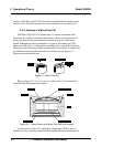
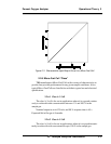
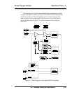
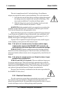
Figure 2-5: Flow Diagram
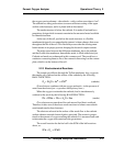
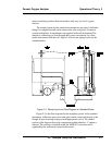
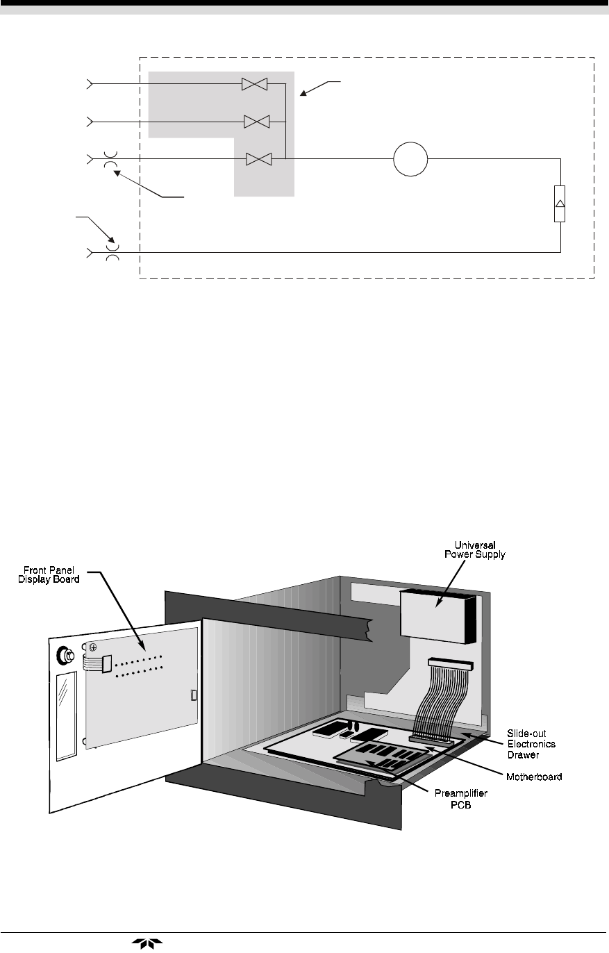
2.4 Electronics and Signal Processing
The Model 3000P Percent Oxygen Analyzer uses an 8031 microcon-
troller with 32 kB of RAM and 128 kB of ROM to control all signal pro-
cessing, input/output, and display functions for the analyzer. System power
is supplied from a universal power supply module designed to be compatible
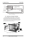
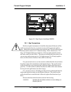
with any international power source. Figure 2-6 shows the location of the
power supply and the main electronic PC boards.
Figure 2-6: Location of Electronic Components
In vacuum service the
restrictor should be
placed here.
Sample In
Span In
Zero In
Flowmeter
Exhaust Out
Solenoid
Valves
Restrictor
Cell
In normal service the
restrictor should be
placed here.
Components in the shaded area are in
the -C option (internal control valves)
only and are not shown in the piping
diagram above.