


932213 Rev. C
20
ENGLISH
VIII.
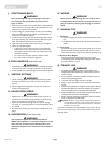
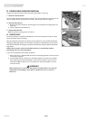
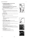
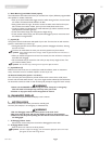
Q. TO ADJUST THE HEIGHT OF THE JOYSTICK
OR ENHANCED DISPLAY (Fig. 23)
1.
Loosen the two Socket Head screws (E).
2. Slide the clamp (F) up or down until in desired position.
3. Retighten the two Socket Head Screws (E).
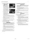
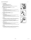
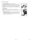
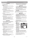
R. JOYSTICK OR ENHANCED DISPLAY SWING-AWAY
RETRACTABLE MOUNT
(Optional) (Fig. 24)
The joystick or Enhanced Display is mounted with a mechanism which allows the control to
be locked in a forward or retracted position using magnets.
Adjustment
a. To retract the joystick or Enhanced Display, push outward on the inside of joystick.
b. Push the joystick or Enhanced Display away from front of armrest until it locks into
retracted position.
c. To return to forward position, push the joystick or Enhanced Display forward until it
locks into place.
S. WHEEL LOCKS
Zippie wheelchairs are shipped with wheel locks. Wheel locks are installed at Sunrise unless
you have requested otherwise.
Use a torque setting of 100 in./lbs when setting-up wheel locks.
1. Wheel Lock
a. Loosen the screws on the top of each clamp. Do not attempt to remove one screw at
a time.
b. Slide assembly toward drive wheel until clamp embeds into tire to prevent wheel
movement when in locked position.
c. Adjust angle position.
d. Tighten screws.
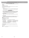
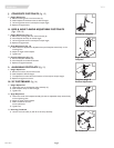
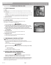
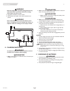
T. ANTI-TIP TUBES - REAR (Manual carrier) (Fig. 25)
1. To Insert Anti-Tip Tubes into Receivers
a) Press the anti-tip release button on the anti-tip tube so that the release pin is drawn
inside.
b) Insert the tube into the anti-tip receiver.
c) Turn the anti-tip tube until release pin is positively engaged in the receiver mounting
hole.
d) Insert second anti-tip tube the same way.
2.
To Adjust Anti-Tip Height
a)
P
ress the anti-tip wheel release button (A) so the release pin is drawn inside.
b) Raise or lower to one of the three pre-drilled holes.
c) Turn the anti-tip tube until release pin is positively engaged in the receiving hole (B).
d)
Adjust the second anti-tip tube wheel the same way
. Both wheels should be exactly the
same height.
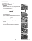
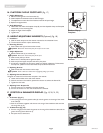
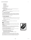
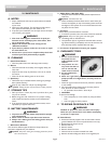
U. SEAT REMOVAL (Figs. 26 & 27)
1. Disconnect joystick.
2. Pull out the safety pin from the left front seat post (Fig. 26).
3.
Lift up on both front seat latches (Fig. 27).
4. Tilt the seat back, slide it forward, and remove from the base.
Anti-Tip Height
A
B
EF
23
24
25
26
27