


ASPIRE SERVICE MANUAL
PAGE 16
2003SUNRISE MEDICAL
Disassembly
Note: For ease of disassembly, set the base frame on a
block where all six wheels are at least 1 inch above the
ground.
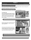
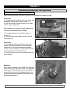
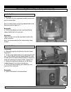
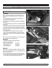
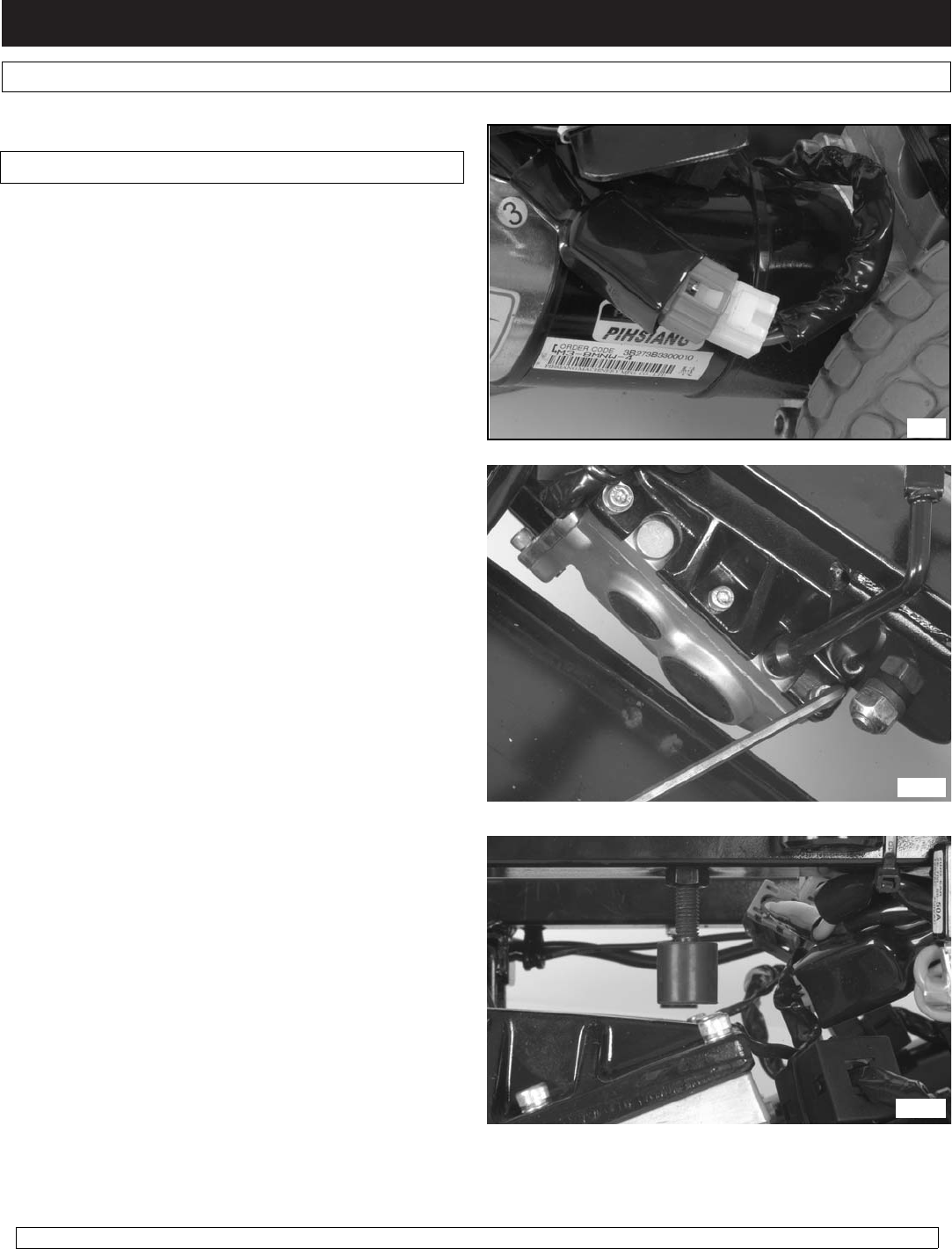
a. Unwrap the wire looms from the motor and pull the
motor connector out (figure s8.1).
b. Depress the motor connector locking tab and unplug it
(figure s8.1).
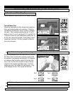
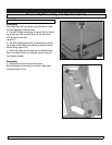
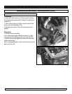
c. Use a 5mm hex key to remove the six mounting screws
(figure s8.2).
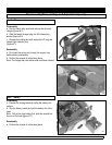
d. Hold the motor-wheel assembly and tilt the cog release
rod toward the center of the base to get around the motor
mount, then pull the motor-wheel assembly out through the
bottom of the frame.
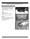
e. Straighten the lock washer tab of the drive wheel.
f. Use a 17mm deep socket wrench to remove the drive
wheel retention nut, then pull the drive wheel out from the
motor shaft.
Note: If the drive wheel is difficult to remove, then remove
the wheel plate screws (Phillips Head)
Reassembly
a. Perform the reverse of instructions above.
Note: Torque specifications
* Motor mounting screws 15-20 ft-lbs
* Wheel retention nut 35-40 ft-lbs
* Wheel plate screw 15-20 ft-lbs
Adjustment
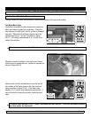
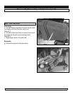
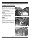
Note: There is a suspension bumper on the frame to limit
the motor’s movement (figure 8.3). It also changes the pre-
load on the front caster.
a. Use a 13mm open wrench to loosen or tighten the jam
nut and make the proper adjustment (operator preference).
b. Install wire tie on back inside corner of gear box.
Step 8 - Motor/Wheel
Disassembly/Reassembly, and Adjustment (cont)
s8.1
s8.2
s8.3