


Guardian Aspire Troubleshooting Guide
INTRODUCTION ......................................................0.1
Specifications
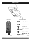
VSI Controller ...........................................................0.2
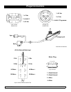
Plugs/Connectors......................................................0.3
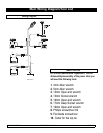
Main Wiring Diagram/Tool List..................................0.4
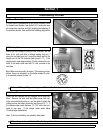
Troubleshooting - No Power .......................Section 1
Step 1.0 Circuit Breaker Reset ...................................1
Step 1.1 Test Joystick .................................................1
Step 1.2 Battery Test ..................................................1
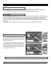
Step 1.3 Recharging the Batteries..............................2
Step 1.4 Not Charging ................................................2
Step 1.5 Battery Connection Check ...........................2
Step 1.6 Battery Wire Harness ....................................3
Step 1.7 Battery Fuse.................................................3
Step 1.8 Circuit Breaker Test......................................3
Step 1.9 Main Harness ...............................................3
Understanding Controller Display ..............Section 2
2.1 Maximum Speed Indicator Ripples.......................4
2.2 Maximum Speed Indicator Flashes ......................4
2.3 Battery Gauge is Steady.......................................4
2.4 Battery Gauge Flashes Slowly .............................4
2.5 Battery Gauge Steps Up.......................................4
2.6 Battery Gauge Blinks Every 2.5 Seconds ............4
2.7 Battery Gauge Flashes Rapily..............................4
Understanding VSI Controller Diagnostics Codes
........................................................................Section 3
3.1 1 Bar (1 Red) Low Battery Voltage .....................5
3.2 2 Bars (2 Red) - Left Motor Disconnected ..........5
3.3 3 Bars (3 Red) - Left Motor Wiring Trip...............6
3.4 4 Bars (3 Red,1 Yellow)
Right Motor Disconnected ...........................................7
3.5 5 Bars (3 Red, 2 Yellow)
Right Motor Wiring Trip................................................8
3.6 7 Bars (3 Red, 4 Yellow)
Possible Joystick Trip ..................................................9
3.7 8 Bars (3 Red, 4 Yellow, 1 Green)
Possible Control System Trip ......................................9
3.8 9 Bars (3 Red, 4 Yellow, 2 Green)
Solenoid Brake Trip .....................................................9
3.9 10 Bars (3 Red, 4 Yellow, 3 Green)
High Battery Voltage..................................................10
Disassembly/Reassembly
and Adjustment.............................................Section 4
Step 1 (Controller and Seat) ......................................11
Step 2 (Cog Release) ................................................12
Step 3 (Seat Posts)....................................................12
Step 4 (Shroud)..........................................................13
Step 5 (Front Caster Cover) ......................................14
Step 6 (Charger) ........................................................15
Step 7 (Battery)..........................................................15
Step 8 (Motor/Wheel).................................................16
Step 9 (Motor Mounts) ...............................................17
Step 10 (Front and Rear Caster Assembly)...............18
Step 11 (Wire Harnesses)..........................................19