


Quantum 610 www.quantumrehab.com 27
V. COMFORT ADJUSTMENTS
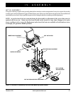
10. Plug the controller connector(s) into the power base.
11. Reinstall the rear shroud and tighten the fasteners.
Foot Platform Height Adjustment
The foot platform height is easily adjusted to different heights
in 1/2-in. increments.
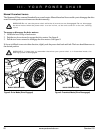
To raise or lower the foot platform:
1. Remove the quick release fasteners from the foot plat-
form bracket. See figure 19.
2. Loosen the foot platform securement nut one-half turn.
3. Raise or lower the foot platform to the desired height.
4. Reinstall the quick release fasteners into the foot plat-
form bracket and tighten.
5. Tighten the nut to secure.
Foot Platform Depth Adjustment
To adjust the foot platform depth:
1. Remove the quick release fasteners from the foot plat-
form bracket. See figure 19.
2. Move the foot platform in or out to the desired depth.
3. Reinstall the quick release fasteners into the foot plat-
form bracket and tighten.
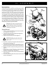
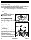
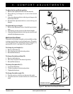
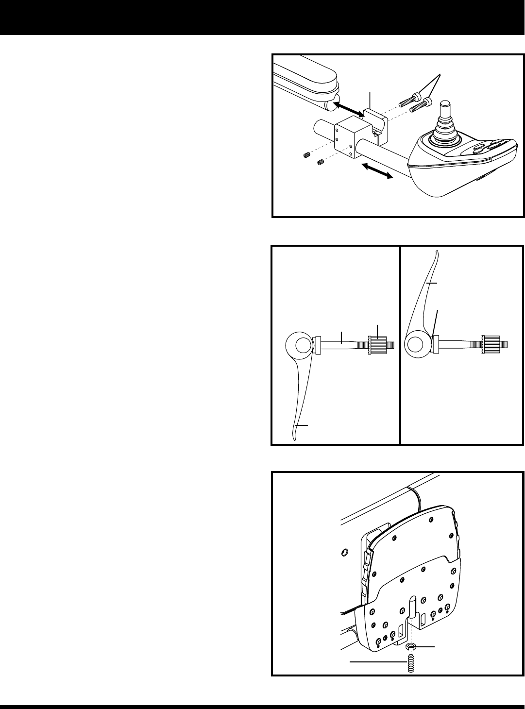
Quick Release Fasteners: The foot platform is attached
to the power base with two quick release fasteners. See
figure 19. Each quick release fastener consists of a bolt, a
lever, and a nut. See figure 22. The lever has a cam on the
end that allows it to clamp into place. The quick release
fastener has two states: clamped and unclamped. When the
lever is open, the quick release fastener is unclamped. When
the lever is closed, the quick release fastener is clamped.
To clamp the quick release fastener:
1. Make sure the lever is in the open position.
2. Turn the nut clockwise until it is snug.
3. Rotate the lever until it is in the fully closed position.
NOTE: If the lever will not rotate to the fully closed
position, then turn the nut counterclockwise one-quar-
ter or one-half turn.
Foot Platform Angle Adjustment
You can adjust the angle of the foot platform with a hex key.
To adjust the foot platform angle:
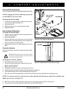
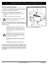
1. Flip up the foot platform and locate the setscrew and
jam nut. See figure 23.
Figure 23. Underside of Foot Platform
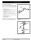
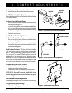
Figure 21. Mounting Block Controller Installation
MOUNTING
SCREWS
MOUNTING
BLOCK
SETSCREW
Figure 22. Quick Release Fastener Operation
LEVER (OPEN)
BOLT
NUT
CAM
UNCLAMPED
CLAMPED
LEVER (FULLY CLOSED)
JAM NUT