


26 www.quantumrehab.com Quantum 610
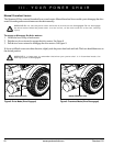
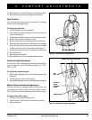
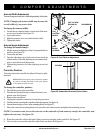
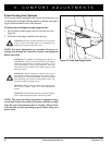
Figure 20. Underside of Armrest (Contour Seat)
SETSCREW
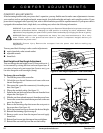
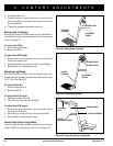
Armrest Width Adjustment
You can change each armrest’s width independently of the other.
NOTE: Changing the armrest width may increase the
overall width of your power chair.
To change the armrest width:
1. Locate the two armrest knobs on each side of the arm-
rest receiver bracket. See figure 18.
2. Loosen the knobs.
3. Slide the armrests in or out to the desired width.
4. Tighten the knobs.
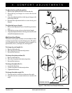
Armrest Angle Adjustment
To change the armrest angle:
1. Lift the armrest straight up so that it is perpendicular to
the floor. See figure 18.
2. Loosen the jam nuts.
3. Turn the adjusting screw clockwise to lower the front
of the armrest, or turn the adjusting screw counterclock-
wise to raise the front of the armrest.
4. Tighten the jam nuts to lock the adjusting screw into
place.
V. COMFORT ADJUSTMENTS
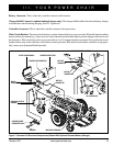
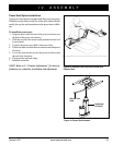
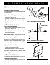
Figure 19. Foot Platform Adjustment
FOOT
PLATFORM
BRACKET
FOOT PLATFORM
RETAINING PIN
QUICK
RELEASE
FASTENERS
SETSCREW
SECUREMENT NUT
Controller Position
You can position the controller for either left-hand or right-
hand use.
WARNING! Do not place the controller cable
so that it can be pinched in the seat frame
or the power base frame.
To change the controller position:
1. Turn off the power to the controller.
2. Turn the rear shroud fasteners counterclockwise one-
quarter turn. See figure 6.
3. Remove the rear shroud.
4. Unplug the controller connector(s) from the power base.
5. Cut the wire tie(s) securing the controller cable to the armrest. See figure 6.
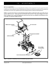
6. Loosen the mounting screws in the mounting block. See figure 21.
7. Move the controller mounting block and controller to the other armrest and tighten the mounting screws.
NOTE: For contour seats, loosen the setscrew on the underside of both armrests, transfer the controller, and
tighten the setscrews. See figure 20.
8. Route the controller cable to the back of the power base and plug in the controller. See figure 12.
9. Use wire ties to secure the controller cable to the seat frame. See figure 13.