Quantum 610 www.quantumrehab.com 19
III. YOUR POWER CHAIR
Battery Connector: This is where the controller connects to the batteries.
Charger Inhibit Connector (optional onboard charger only): The charger inhibit enables the onboard battery charger
to disable the controller during charging. See VII. “Operation.”
Controller Connector: This is where the controller connects to the power base.
Main Circuit Breaker: The main circuit breaker is a safety feature built into your power chair. When the batteries and the
motors are heavily strained (e.g., from excessive loads), the main circuit breaker trips to prevent damage to the motors and
the electronics. If the circuit trips, allow your power chair to “rest” for approximately one minute. Next, push in the circuit
breaker button, turn on the controller, and continue normal operation. If the main circuit breaker continues to trip repeat-
edly, contact your Quantum Rehab Specialist.
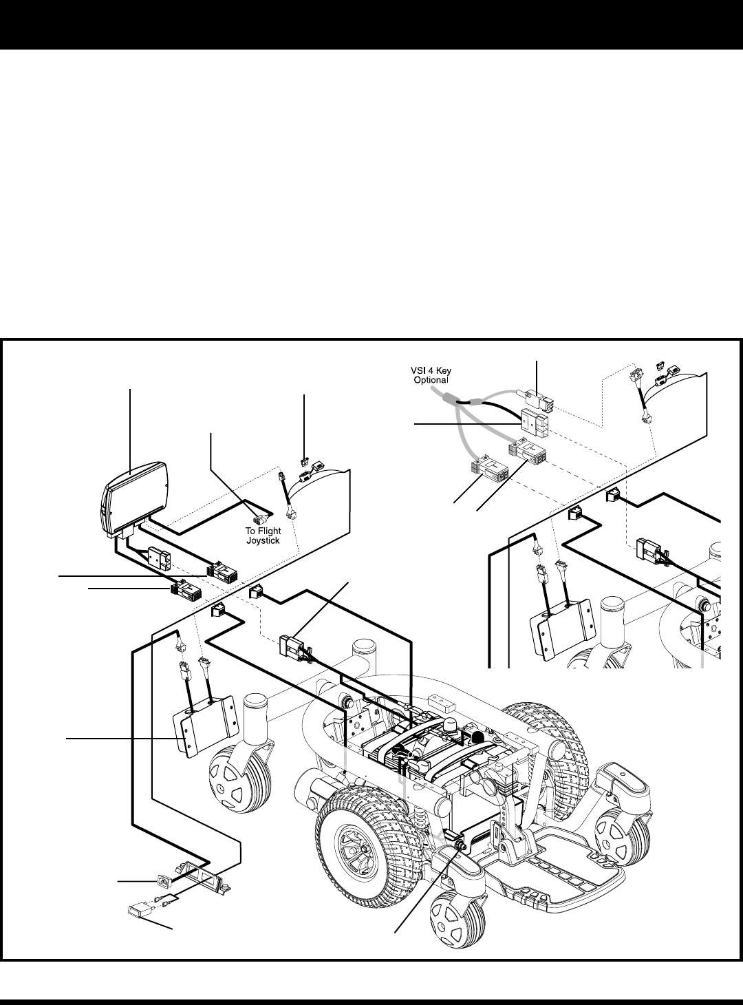
Figure 7. Quantum 610 Electrical Components (Shown With Optional Onboard Battery Charger)
BATTERY
CONNECTOR
CHARGER POWER
CORD RECEPTACLE
CHARGER CIRCUIT FUSE
ONBOARD BATTERY
CHARGER
MAIN CIRCUIT BREAKER
AMMETER
FLIGHT POWER MODULE
MOTOR
CONNECTORS
CHARGER INHIBIT CONNECTOR
BATTERY
CONNECTOR
VSI CONTROLLER
CONTROLLER CONNECTOR
MOTOR
CONNECTORS


