


18 www.pridemobility.com Jazzy 1101/1121/Rev E/Jun03
IV. THE JAZZY 1101/1121
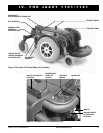
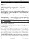
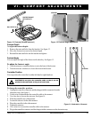
Electronics Tray
The electronics tray is located on the back of the power base. See figures 3 and 4. The ammeter, the onboard charger AC
power cord, the main circuit breaker, the controller connector, and the charger fuse are all located on the electronics tray.
Ammeter: The ammeter displays the chargers current output in amps. See VII. Batteries and Charging.
Onboard Charger AC Power Cord Receptacle: This is where the onboard charger AC power cord plugs into the
power base.
Main Circuit Breaker: The main circuit breaker is a safety feature built into your Jazzy. When the batteries and the
motors are heavily strained (e.g., from excessive loads), the main circuit breaker trips to prevent damage to the motors and
the electronics. If the circuit trips, allow your Jazzy to rest for approximately one minute. Next, push in the circuit breaker
button, turn on the controller, and continue normal operation. If the main circuit breaker continues to trip repeatedly,
contact your authorized Pride Provider.
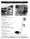
Controller Connector: This is where the controller connects to the power base. The VSI controller uses a large 9-pin
connector. The Remote Plus and the Europa use smaller, multi-pin communications cable connectors (not shown).
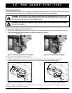
Charger Inhibit Connector: The VSI controller is equipped with a charger inhibit connector. The charger inhibit
enables the onboard charger to disable the controller during charging. The charger inhibit connector is coded with
colored dots. The dots are positioned so that you can align the flat side of the male connector with the flat side of
the female connector before making the connection.
CAUTION! Failure to properly align the connectors can result in damage to the controller, the charger
harness, and the connectors.
Charger Fuse: The charger fuse protects the ammeter from current overload. There are three fuses on the utility tray. The
top one is the charger fuse. The bottom two are spares.
Power Actuator Connector and Lighting System Connector (VSI Only): This is where the power actuator connects
to the controller. Standard lighting systems have a single-pin connector. Full lighting systems with the VSI controller use a
3-pin connector. Not shown.
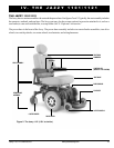
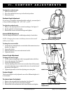
Active-Trac Suspension (1121 Only)
The Jazzy 1121 is equipped with Active-Trac Suspension (ATS). ATS is a suspension system designed to make your Jazzy
traverse different types of terrain and obstacles while maintaining smooth operation. With ATS, your front anti-tip wheels
work in conjunction with your motor suspension to help you maneuver over obstacles in excess of three inches in height.
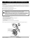
As your front anti-tip wheels come in contact with an obstacle, the front anti-tip wheel assembly is drawn upward. At the
same time, your motors are forced downward. This allows the motors to push the Jazzy 1121 over an obstacle without the
possibility of becoming hung up on the obstacle.
ATS also helps in day-to-day operating conditions. For instance, when you release the joystick, your Jazzy begins to slow
down. As the chair slows down, the front anti-tip wheels will automatically drop toward the ground. This will reduce the
forward tip that is typically encountered with center-wheel drive chairs.