


30 www.pridemobility.com Jazzy 1100/RevJ/Feb03
VIII. OPERATION
n Red, yellow, and green lights lit: Battery charged; Pilot and electrical system OK.
n Red and yellow lights lit: Charge battery if possible; Pilot and electrical system OK.
n Red lights only lit or slow flash: Charge battery as soon as possible; Pilot and electrical system OK.
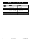
n Rapid flash of lights: Indicates a fault in the Pilot or the electrical system. Refer to Pilot Error
Codes.
n Ripple up and down of lights: The joystick was not in the neutral position when the controller was
turned on. If you get ripple up and down of lights, turn off the controller, allow the joystick to return
to the neutral position, then turn on the controller.
NOTE: If you still get ripple up and down of lights, contact your authorized Pride Provider.
NOTE: When the batteries approach a discharged state, the first red light will begin to slowly flash,
reminding you the batteries need to be charged immediately!
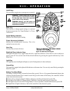
Speed Control Knob
Sets the maximum speed of the power chair: clockwise to increase, counterclockwise to decrease.
NOTE: We recommend that the first few times you operate your power chair, you turn the speed control
to the slowest setting until you become familiar with your new power chair.
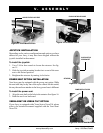
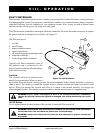
Off-board Charger/Programming Socket
You may use an off-board charger to charge the power chair batteries through the 3-pin socket located on
the front of the Pilot. If you use an off-board charger, the charger current should not exceed 13 amps.
Contact your authorized Pride provider for more information.
CAUTION! Only chargers with Neutrik NC3MX plugs should be connected to the off-board
charger/programming socket. See your authorized Pride provider for more information.
NOTE: The offboard charger/programming socket may also be used for reprogramming the Pilot.
Contact your authorized Pride provider for more information.
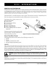
Controller Connector
This connects the Pilot to the power chairs batteries, motors, and motor brakes.
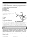
3-pin Charger Inhibit Connector
This connects the Pilot to the onboard battery charger. This connection provides an inhibit that disables the
Pilot when the battery charger is on. The charger inhibit connector is coded with colored dots. The dots are
positioned so that you align the flat side of the male connector with the flat side of the female connector
before making the connection.
Battery Condition Meter
The battery condition meter is located in front of the joystick. This is a 10-segment illuminated display that
indicates that the Pilot is turned on and also gives the battery status, the Pilot status, and the electrical
system status.