


Philips Semiconductors
User’s Manual - Preliminary -
P89LPC901/902/903
CLOCKS
2003 Dec 8 27
2. CLOCKS
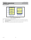
Enhanced CPU
The P89LPC901/902/903 uses an enhanced 80C51 CPU which runs at 6 times the speed of standard 80C51 devices. A machine
cycle consists of two CPU clock cycles, and most instructions execute in one or two machine cycles.
Clock Definitions
The P89LPC901/902/903 device has several internal clocks as defined below:
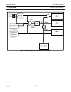
• OSCCLK - Input to the DIVM clock divider. OSCCLK is selected from one of the clock sources (see Figure 2-3,Figure 2-
4,Figure 2-5) and can also be optionally divided to a slower frequency (see section "CPU Clock (CCLK) Modification: DIVM
Register"). Note: f
OSC
is defined as the OSCCLK frequency.
• XCLK - Output of the crystal oscillator (P89LPC901)
• CCLK - CPU clock.
• PCLK - Clock for the various peripheral devices and is CCLK/2
CPU Clock (OSCCLK)
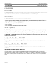
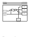
The P89LPC901 provides several user-selectable oscillator options. This allows optimization for a range of needs from high
precision to lowest possible cost. These options are configured when the FLASH is programmed and include an on-chip
watchdog oscillator, an on-chip RC oscillator, an oscillator using an external crystal, or an external clock source. The crystal
oscillator can be optimized for low, medium, or high frequency crystals covering a range from 20 kHz to 12 MHz.
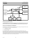
The P89LPC902 and P89LPC903 devices allow the user to select between an on-chip watchdog oscillator and an on-chip RC
oscillator as the CPU clock source.
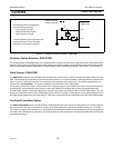
Low Speed Oscillator Option - P89LPC901
This option supports an external crystal in the range of 20 kHz to 100 kHz. Ceramic resonators are also supported in this
configuration.
Medium Speed Oscillator Option - P89LPC901
This option supports an external crystal in the range of 100 kHz to 4 MHz. Ceramic resonators are also supported in this
configuration.
High Speed Oscillator Option - P89LPC901
This option supports an external crystal in the range of 4MHz to 12 MHz. Ceramic resonators are also supported in this
configuration. If CCLK is 8MHz or slower, the CLKLP SFR bit (AUXR1.7) can be set to ’1’ to reduce power consumption. On
reset, CLKLP is ’0’ allowing highest performance access. This bit can then be set in software if CCLK is running at 8MHz or
slower.