


Philips Semiconductors
User’s Manual - Preliminary -
P89LPC901/902/903
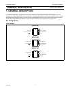
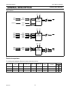
GENERAL DESCRIPTION
2003 Dec 8 13
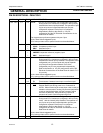
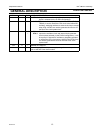
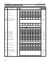
O XTAL2 Output from the oscillator amplifier (when a crystal oscillator
option is selected via the FLASH configuration).
OCLKOUTCPU clock divided by 2 when enabled via SFR bit (ENCLK -
TRIM.6). It can be used if the CPU clock is the internal RC
oscillator, watchdog oscillator or external clock input, except
when XTAL1/XTAL2 are used to generate clock source for
the Real-Time clock/system timer.
2I/OP3.1 Port 3 bit 1.
I XTAL1 Input to the oscillator circuit and internal clock generator
circuits (when selected via the FLASH configuration). It can
be a port pin if internal RC oscillator or watchdog oscillator
is used as the CPU clock source, AND if XTAL1/XTAL2 are
not used to generate the clock for the Real-Time clock/
system timer.
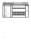
V
SS
8IGround: 0V reference.
V
DD
1IPower Supply: This is the power supply voltage for normal operation as
well as Idle and Power down modes.
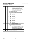
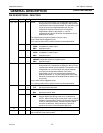
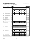
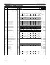
MNEMONIC PIN NO. TYPE NAME AND FUNCTION