


Philips Semiconductors
User’s Manual - Preliminary -
P89LPC901/902/903
REAL-TIME CLOCK/SYSTEM TIMER
2003 Dec 8 51
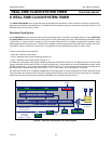
6. REAL-TIME CLOCK/SYSTEM TIMER
The P89LPC901/902/903 has a simple Real-time clock/system timer that allows a user to continue running an accurate timer
while the rest of the device is powered down. The Real-time clock can be an interrupt or a wake-up source (see Figure 6-1). The
Real-time clock is a 23-bit down counter.
Real-time Clock Source
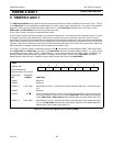
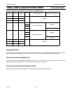
On the P89LPC901 the clock source for this counter can be either CCLK or the XTAL1-2 oscillator (XCLK) . On the P89LPC902
and P89LPC903 devicesthe clock source for this counter is CCLK. Please refer to Figure 2-3 "Block Diagram of Oscillator Control
- P89LPC901" in section "Clocks" on page 27. CCLK can have either the XTAL1-2 oscillator, the internal RC oscillator, or the
Watchdog oscillator as its clock source. If the XTAL1-2 oscillator is used for producing CCLK, the RTC will use either the XTAL1-
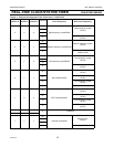
2 oscillator’s output or CCLK as its clock source. The possible clocking combinations are shown in Table , below.
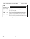
There are three SFRs used for the RTC:
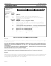
• RTCCON - Real-time clock control.
• RTCH - Real-time clock counter reload high (bits 22-15).
• RTCL - Real-time clock counter reload low (bits 14-7).
The Real-time clock/system timer can be enabled by setting the RTCEN (RTCCON.0) bit. The Real-time clock is a 23-bit down
counter (initialized to all 0’s when RTCEN = 0) that is comprised of a 7-bit prescaler and a 16-bit loadable down counter. When
RTCEN is written with ’1’, the counter is first loaded with (RTCH,RTCL,’1111111’) and will count down. When it reaches all 0’s,
the counter will be reloaded again with (RTCH,RTCL,’1111111’) and a flag - RTCF (RTCCON.7) - will be set.
Any write to RTCH and RTCL in-between the Real-time clock reloading will not cause reloading of the counter. When the current
count terminates, the contents of RTCH and RTCL will be loaded into the counter and the new count will begin. An immediate
reload of the counter can be forced by clearing the RTCEN bit to ’0’ and then setting it back to ’1’ .
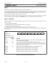
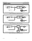
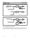
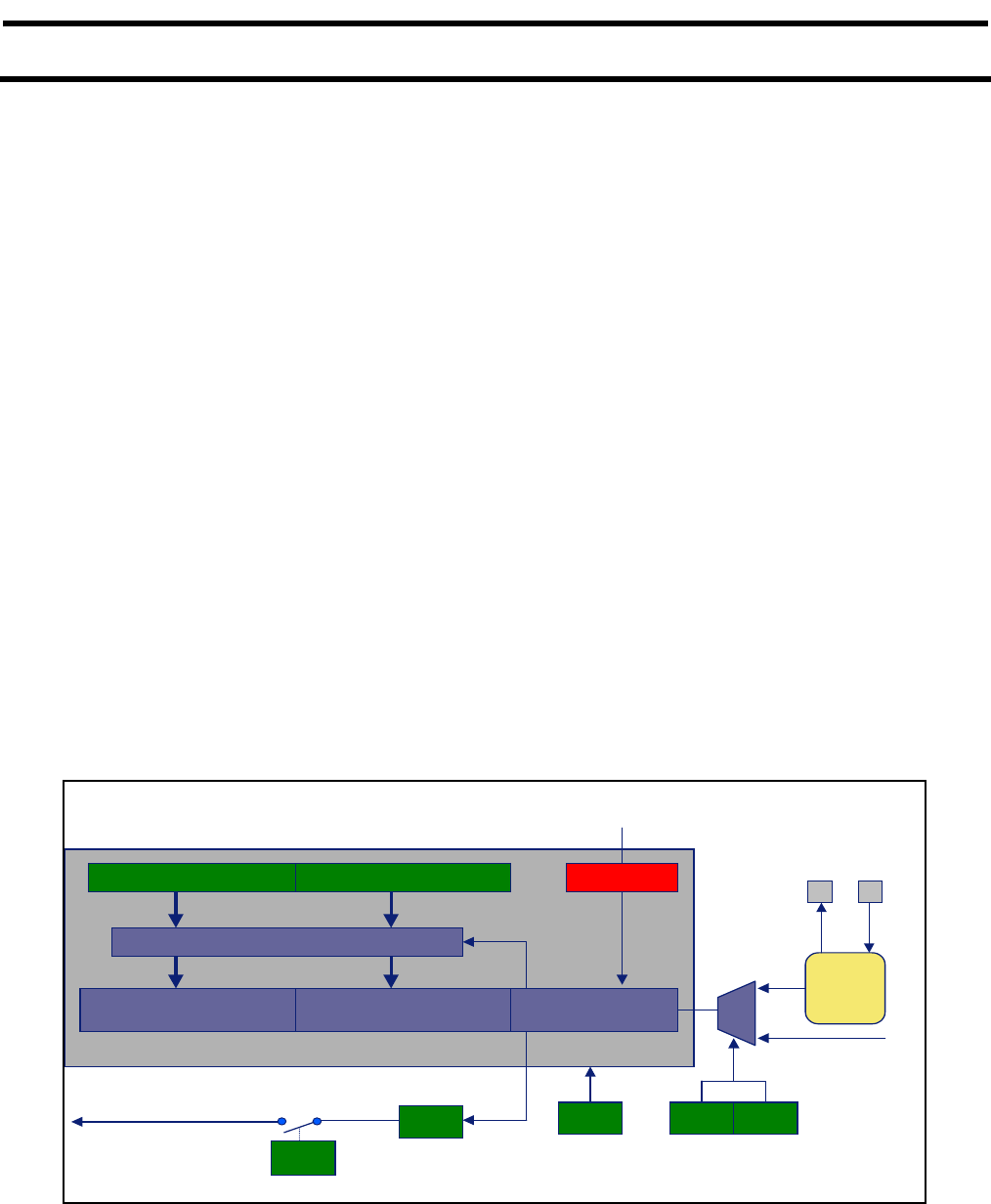
Figure 6-1: Real-time clock/system timer Block Diagram
23-bit down counter
7-bit prescaler
RTCH RTCL
Interrupt
if enabled
(shared w. WDT)
Power-On
Reset
Low freq.
Med. freq.
High freq.
CCLK
XTAL1XTAL2
RTCEN
LSB
RTC underflow flag
ERTC
RTCF
RTCS1 RTCS2
RTC clk select
RTC Enable
Wake up from
Power-down
Int. Osc’s
MSB
÷ 128
RTC Reset
Reload on underflow