


Philips Semiconductors
User’s Manual - Preliminary -
P89LPC901/902/903
INTERRUPTS
2003 Dec 8 35
3. INTERRUPTS
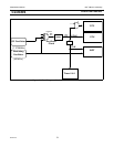
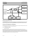
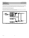
The P89LPC901/902/903 use a four priority level interrupt structure. This allows great flexibility in controlling the handling of the
many interrupt sources. The P89LPC901 supports 6 interrupt sources: timers 0 and 1, brownout detect, watchdog/ realtime
clock, keyboard, and the comparator. The P89LPC902 supports 6 interrupt sources: timers 0 and 1, brownout detect, watchdog/
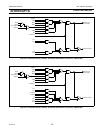
realtime clock, keyboard, and comparators 1 and 2. The P89LPC903 supports 9 interrupt sources: timers 0 and 1, serial port
Tx, serial port Rx, combined serial port Rx/Tx, brownout detect, watchdog/ realtime clock, keyboard, and comparators 1 and 2.
Each interrupt source can be individually enabled or disabled by setting or clearing a bit in the interrupt enable registers IEN0 or
IEN1. The IEN0 register also contains a global enable bit, EA, which enables all interrupts.
Each interrupt source can be individually programmed to one of four priority levels by setting or clearing bits in the interrupt priority
registers IP0, IP0H, IP1, and IP1H. An interrupt service routine in progress can be interrupted by a higher priority interrupt, but
not by another interrupt of the same or lower priority. The highest priority interrupt service cannot be interrupted by any other
interrupt source. If two requests of different priority levels are pending at the start of an instruction, the request of higher priority
level is serviced.
If requests of the same priority level are pending at the start of an instruction, an internal polling sequence determines which
request is serviced. This is called the arbitration ranking. Note that the arbitration ranking is only used to resolve pending requests
of the same priority level.
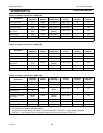
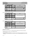
Table summarizes the interrupt sources, flag bits, vector addresses, enable bits, priority bits, arbitration ranking, and whether
each interrupt may wake up the CPU from a Power down mode.
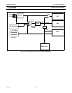
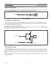
Interrupt Priority Structure
There are four SFRs associated with the four interrupt levels: IP0, IP0H, IP1, IP1H. Every interrupt has two bits in IPx and IPxH
(x = 0,1) and can therefore be assigned to one of four levels, as shown in Table .
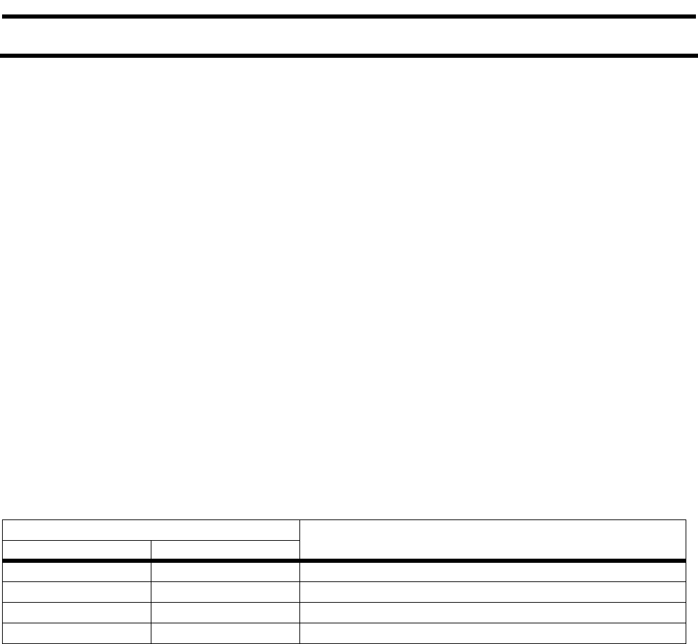
Table 3-1: Interrupt priority level
Priority Bits
Interrupt Priority Level
IPxH IPx
0 0 Level 0 (lowest priority)
0 1 Level 1
1 0 Level 2
1 1 Level 3 (highest priority)