


Philips Semiconductors
User’s Manual - Preliminary -
P89LPC901/902/903
List of Figures
2003 Dec 8 5
List of Figures
P89LPC901/902/903 Memory Map. . . . . . . . . . . . . . . . . . . . . . . . . . . . . . . . . . . . . . . . . . 25
Using the Crystal Oscillator - P89LPC901 . . . . . . . . . . . . . . . . . . . . . . . . . . . . . . . . . . . . 28
On-Chip RC Oscillator TRIM Register. . . . . . . . . . . . . . . . . . . . . . . . . . . . . . . . . . . . . . . . 29
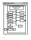
Block Diagram of Oscillator Control - P89LPC901 . . . . . . . . . . . . . . . . . . . . . . . . . . . . . . 30
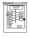
Block Diagram of Oscillator Control - P89LPC902 . . . . . . . . . . . . . . . . . . . . . . . . . . . . . . 31
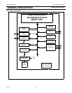
Block Diagram of Oscillator Control- P89LPC903. . . . . . . . . . . . . . . . . . . . . . . . . . . . . . . 32
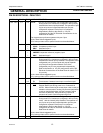
Interrupt priority level. . . . . . . . . . . . . . . . . . . . . . . . . . . . . . . . . . . . . . . . . . . . . . . . . . . . . 35
Summary of Interrupts - P89LPC901 . . . . . . . . . . . . . . . . . . . . . . . . . . . . . . . . . . . . . . . . 36
Summary of Interrupts - P89LPC903 . . . . . . . . . . . . . . . . . . . . . . . . . . . . . . . . . . . . . . . . 36
Summary of Interrupts - P89LPC902 . . . . . . . . . . . . . . . . . . . . . . . . . . . . . . . . . . . . . . . . 36
Interrupt sources, enables, and Power down Wake-up sources - P89LPC901 . . . . . . . . 37
Interrupt sources, enables, and Power down Wake-up sources - P89LPC902 . . . . . . . . 38
Interrupt sources, enables, and Power down Wake-up sources - P89LPC903 . . . . . . . . 38
Number of I/O Pins Available . . . . . . . . . . . . . . . . . . . . . . . . . . . . . . . . . . . . . . . . . . . . . . 39
Port Output Configuration Settings. . . . . . . . . . . . . . . . . . . . . . . . . . . . . . . . . . . . . . . . . . 39
Quasi-Bidirectional Output . . . . . . . . . . . . . . . . . . . . . . . . . . . . . . . . . . . . . . . . . . . . . . . . 40
Open Drain Output . . . . . . . . . . . . . . . . . . . . . . . . . . . . . . . . . . . . . . . . . . . . . . . . . . . . . . 40
Input Only . . . . . . . . . . . . . . . . . . . . . . . . . . . . . . . . . . . . . . . . . . . . . . . . . . . . . . . . . . . . . 41
Push-Pull Output . . . . . . . . . . . . . . . . . . . . . . . . . . . . . . . . . . . . . . . . . . . . . . . . . . . . . . . . 41
Port Output Configuration - P89LPC901. . . . . . . . . . . . . . . . . . . . . . . . . . . . . . . . . . . . . . 42
Port Output Configuration - P89LPC902. . . . . . . . . . . . . . . . . . . . . . . . . . . . . . . . . . . . . . 42
Port Output Configuration - P89LPC903. . . . . . . . . . . . . . . . . . . . . . . . . . . . . . . . . . . . . . 42
Timer/Counter Mode Control register (TMOD) . . . . . . . . . . . . . . . . . . . . . . . . . . . . . . . . . 45
Timer/Counter Auxiliary Mode Control register (TAMOD). . . . . . . . . . . . . . . . . . . . . . . . . 46
Timer/Counter Control register (TCON) . . . . . . . . . . . . . . . . . . . . . . . . . . . . . . . . . . . . . . 47
Timer/Counter 0 or 1 in Mode 0 (13-bit counter). . . . . . . . . . . . . . . . . . . . . . . . . . . . . . . . 48
Timer/Counter 0 or 1 in Mode 1 (16-bit counter). . . . . . . . . . . . . . . . . . . . . . . . . . . . . . . . 48
Timer/Counter 0 or 1 in Mode 2 (8-bit auto-reload). . . . . . . . . . . . . . . . . . . . . . . . . . . . . . 48
Timer/Counter 0 Mode 3 (two 8-bit counters) . . . . . . . . . . . . . . . . . . . . . . . . . . . . . . . . . . 49
Timer/Counter 0 in Mode 6 (PWM auto-reload), P89LPC901. . . . . . . . . . . . . . . . . . . . . . 49
Real-time clock/system timer Block Diagram . . . . . . . . . . . . . . . . . . . . . . . . . . . . . . . . . . 51
Real-time Clock/System Timer Clock Source - P89LPC901 . . . . . . . . . . . . . . . . . . . . . . 52
:Real-time Clock/System Timer Clock Source - P89LPC902/903 . . . . . . . . . . . . . . . . . . 53
RTCCON Register. . . . . . . . . . . . . . . . . . . . . . . . . . . . . . . . . . . . . . . . . . . . . . . . . . . . . . . 54
Brownout Options.. . . . . . . . . . . . . . . . . . . . . . . . . . . . . . . . . . . . . . . . . . . . . . . . . . . . . . . 56
Power Reduction Modes. . . . . . . . . . . . . . . . . . . . . . . . . . . . . . . . . . . . . . . . . . . . . . . . . . 57
Power Control Register (PCON) . . . . . . . . . . . . . . . . . . . . . . . . . . . . . . . . . . . . . . . . . . . . 58
Power Control Register (PCONA). . . . . . . . . . . . . . . . . . . . . . . . . . . . . . . . . . . . . . . . . . . 59
SFR Locations for UARTs. . . . . . . . . . . . . . . . . . . . . . . . . . . . . . . . . . . . . . . . . . . . . . . . . 62
Baud Rate Generation for UART. . . . . . . . . . . . . . . . . . . . . . . . . . . . . . . . . . . . . . . . . . . . 62
BRGCON Register . . . . . . . . . . . . . . . . . . . . . . . . . . . . . . . . . . . . . . . . . . . . . . . . . . . . . . 63
Baud Rate Generations for UART (Modes 1, 3) . . . . . . . . . . . . . . . . . . . . . . . . . . . . . . . . 63
Serial Port Control Register (SCON). . . . . . . . . . . . . . . . . . . . . . . . . . . . . . . . . . . . . . . . . 64