


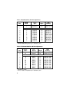
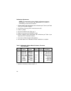
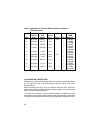
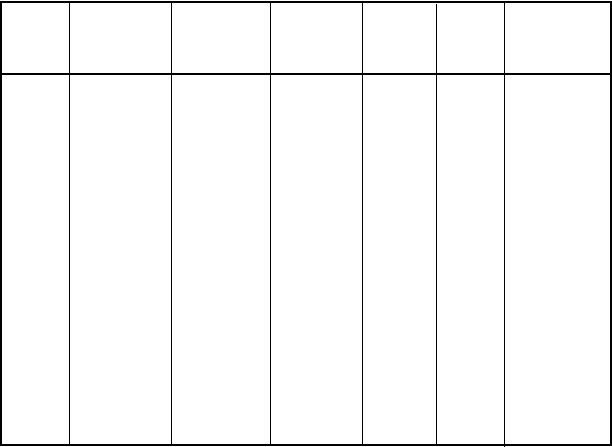
Current
Sensor Unit Source DMM
Step Select Output Input Adjust Verify Reading*
1 RTD-100 1562.0°F 1mA P38 0.39026v
2 RTD-100 32.0°F 1mA √ 0.10000
±0.00006v
3 RTD-100 –328.0°F 1mA √ 0.01849
±0.00012v
4 1,000Ω 900.00Ω 1mA √ 0.90000
±0.00020v
5 1,000Ω 1.00Ω 1mA √ 0.00100
±0.00020v
6 100,000Ω 90,000Ω 10µA P51 0.90000v
7 100,000Ω 100Ω 10µA √ 0.00100
±0.00020v
8 Thermistor 293.0°F 1mA √ 0.04700
±0.00020v
9 Thermistor 77.0°F 10µA √ 0.02252
±0.00020v
10 Thermistor –40.0°F 10µA √ 0.75790
±0.00500v
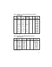
Table 6: Calibration of Calibrator-Mode Resistance Functions
(RTD-Thermistor)
* exclusive of noise.
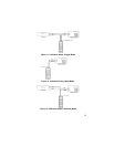
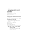
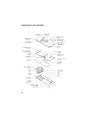
2. CALIBRATION VERIFICATION
Calibration is verified with the same instrument hookups as used for calibra-
tion (ie. Figures 12 and 13 for thermocouple functions, Figure 14 for resis-
tance functions).
While one hookup serves to verify all resistance functions (RTD, thermistor,
ohms), a full check-out of thermocouple functions requires a set of calibration
cables for each thermocouple type.
To simplify the verification of thermocouple calibration, software has been
enhanced to reactivate the copper-mode used during calibration. This feature
is available on products that use the following (and later) software revisions:
32