


Calibration Adjustments:
NOTE: Do not deviate from the calibration adjustment sequence
that follows. This will ensure that adjustments to be stored in
EEPROM go to the correct locations.
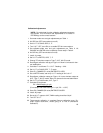
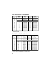
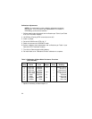
1. Set meter-mode zero and gain adjustments per Table 1.
2. Hit OPR key (RTD annunciator turns off).
3. Set U.U.T. to CALIB, OPR, K, °F.
4. Turn U.U.T. OFF, then ON, to re-enable RTD & Ω annunciators.
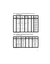
5. Set calibrator-mode zero and gain adjustments per Table 2. Hit
CHANGE and ENTER at the completion of each step in Table 2.
6. Hit OPR key (RTD annunciator turns off).
7. Install J1 jumper.
8. Set U.U.T. to METER, OPR, T, °F
9. Change TC simulator output to Type T, 32°F, ALLOY mode.
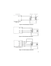
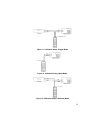
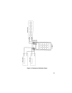
10. Reconfigure calibration set-up per Figure 12. Allow 2-3 minutes for ther-
mal stabilization.
11. Calculate E1 as follows: E1 = U.U.T. Reading — 32.0.
12. Set U.U.T. to CALIB, OPR, T, °F mode.
13. Store E1; CHANGE/(E1 value)/ENTER/STO/1/OPR.
14. Go to METER mode, and verify U.U.T. reading of 32.0 ±0.1°F.
15. Reconfigure calibration setup per Figure 12. Leave simulator output at
32°F, Type T, ALLOY mode. Allow 2-3 minutes for thermal stabilization.
16. Set U.U.T. to CALIB mode, 32°F, Type T.
17. Calculate E2 as follows:
E2 =
DMM Reading (in µV)
–22
(For example with DMM reading of +11µV, E2 = –0.5°F)
18. Store E2; CHANGE/(E2 value)/ENTER/STO/2/OPR.
19. Install J2 jumper.
20. Re-set U.U.T. output to 32°F, DMM reading should be 0±2µV.
21. Turn OFF U.U.T.
22. Thermocouple calibration is complete. Remove calibration cover. Re-
install original back-cover, unless going on to Part B (Resistance
Calibration).
25