


24
NOTE: For calibrators with the older, single-jumper configura-
tion, refer to calibration procedure beginning on page 39.
14. Install calibration cover in place of bottom-cover.
15. Re-install battery.
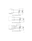
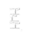
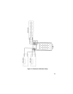
16. Hook up test-equipment, calibration cables, and U.U.T. per Figure 10.
17. Turn on DMM and TC simulator for warmup. Allow at least 30 minutes.
18. Set the DMM to 200mV DC range.
19. Set the TC simulator to its COPPER output mode, with a reference tem-
perature of 32.0°F.
10. Turn on U.U.T. and verify that "RTD" and "Ω" annunciators are flashing
on the display. This verifies removal of J1 and J2 respectively.
NOTE: Flashing “RTD” indicates that zero-offset corrections can
be stored in EEPROM. It also indicates that cold-junction com-
pensation is disabled.
Flashing 'Ω' indicates that error corrections for the cold-junction
sensors can be stored or recalled from EEPROM.
11. Clear the EEPROM locations used to store E1 (meter cold-junction sen-
sor error) and E2 (calibrator cold-junction sensor error) as follows:
a. Set U.U.T to CALIB, OPR, K, °F mode.
b. Key in: CHANGE/0.0/ENTER/STO/1/OPR (E1 is set to 0.0°F)
c. Key in: CHANGE/0.0/ENTER/STO/2/OPR (E2 is set to 0.0°F)
NOTE: Both 1 & 2 memory annunciators should be turned on,
but the “RTD” annunciator will have turned off.
d. Perform RECALL 1 and RECALL 2 to verify storage of 0.0°F in both
locations.
NOTE: At the completion of calibration, E1 and E2 will be saved
in EEPROM. Memory locations 1 and 2 will be free for normal
use.
e. Set U.U.T. to METER, OPR, K, °F.
f. Turn U.U.T. OFF, then ON to re-enable 'RTD' and 'Ω' annunciators.