


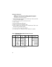

Sensor Unit Unit
Step Select Input Adjust Verify Reading*
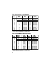
1 RTD-100 390.26Ω P1** 1562.0°F±0.5°F
2 RTD-100 100.00Ω √ 32.0±0.1°F
3 RTD-100 18.49Ω √ –328.0±0.2°F
4 RTD-1000 3,902.6Ω P1** 1562.0°F±0.5°F
5 RTD-1000 1000.0Ω √ 32.0+0.1°F
6 1,000Ω 900.00Ω P1 900.00Ω
7 1,000Ω 1.00Ω √ 1.00±0.10Ω
8 10,000Ω 9,000.0Ω P1 9000.0Ω
9 10,000Ω 10.0Ω √ 10.0±1.0Ω
Table 3: Calibration of Meter-Mode Resistance Functions
(RTD-100/1000)
* exclusive of noise.
** adjust as necessary to obtain steps 2, 5.
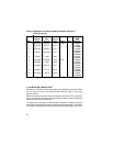
Calibration Adjustments:
NOTE: Do not deviate from the calibration adjustment sequence
that follows. This will ensure that adjustments to be stored in
EEPROM go to the correct locations.
1. Perform meter-mode adjustments and verifications per Table 3 (use Table
5 for RTD-Thermistor models).
2. Hit OPR key (Flashing 'RTD' annunciator turns off).
3. Install J1 jumper.
4. Set unit to CALIB mode, RTD-100, °F.
5. Switch current source to OPERATE mode.
6 Perform calibrator-mode adjustments and verifications per Table 4 (use
Table 6 for RTD-Thermistor models).
7. Turn off unit. Remove tape holding battery.
8. Re-install back cover. Resistance-function calibration is complete.
30