


© National Instruments Corp. 9 FP-PG-522 and cFP-PG-522
values, which reflect the number of pulses each channel has left to
generate after the current pulse. When you send the Generate
Pulses command to one of these channels, the data immediately
changes to reflect the number of pulses that remain. The data value
starts at the total number of pulses minus 1 and is zero during the
last pulse. For channels generating pulses in Continuous mode, the
data value is always zero.
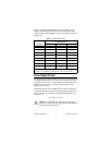
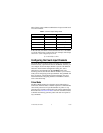
Channels 8–15 correspond to physical channels 0–7. These
channels are not associated with any configuration attributes or
commands. The data values for channels 8–15 are Boolean values
that reflect the state of the physical outputs. Table 4 shows the
relationship between physical channels and the channels seen from
the FieldPoint software.
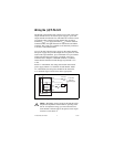
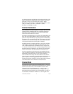
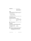
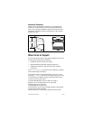
Status Indicators
Figure 4 shows the status indicator LEDs on the [c]FP-PG-522.
Figure 4. Status Indicators
The [c]FP-PG-522 has two green status LEDs, POWER and
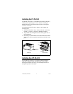
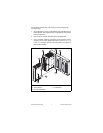
READY. After you insert the FP-PG-522 into a terminal base or
the cFP-PG-522 onto a backplane and apply power to the
connected network module, the green POWER indicator lights
and the [c]FP-PG-522 informs the network module of its presence.
Table 4. Relationship of Physical and Software Channels
Physical Channel Pulse Channel Output State Channel
0 0 8
1 1 9
2 2 10
3 3 11
4 4 12
5 5 13
6 6 14
7 7 15