


© National Instruments Corp. 5 FP-PG-522 and cFP-PG-522
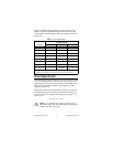
Table 1 lists the terminal assignments for the signals of each
channel. Terminal assignments are also listed on the side panel
of the cFP-PG-522 and under the slide-in card on the front of the
FP-PG-522.
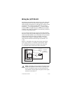
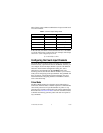
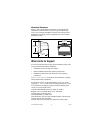
Pulse Output Circuit
The [c]FP-PG-522 output channels are optically isolated from the
rest of the FieldPoint bank. In the ON state, a transistor is turned
on between the output (V
OUT
) and common (C and COM). In the
OFF state, this transistor is turned off, allowing only a small
leakage current to flow.
Ensure that the load on any channel does not draw more than 2 A.
In addition, the sum of the squares of the channel currents must
not exceed 16 A
2
. For example, five channels operating at 1.2 A
yields 7.2 A
2
:
(1.2 A)
2
× 5 = 7.2 A
2
Caution For a cFP-PG-522 operating in the 60–70 °C
temperature range, the sum of the squares of the channel
currents must not exceed 8 A
2
.
Table 1. Terminal Assignments
Channel
Terminal Numbers
V
OUT
1
V
SUP
2
COM
0 2 1,17 18
1 4 3,19 20
2 6 5,21 22
3 8 7,23 24
4 10 9,25 26
5 12 11,27 28
6 14 13,29 30
7 16 15,31 32
1
Install a 2 A maximum, fast-acting fuse on each V
OUT
terminal.
2
Install a 2 A maximum, fast-acting fuse on each V
SUP
terminal.