


FP-PG-522 and cFP-PG-522 4 ni.com
Wiring the [c]FP-PG-522
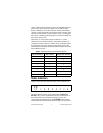
The FP-TB-x terminal base has connections for each of the eight
output channels and for an external power supply to power the
output channels and field devices. The cFP-CB-x connector block
provides the same connections. Each channel has one output
terminal (V
OUT
), two supply terminals (V
SUP
), and one common
terminal (COM). All eight channels are referenced to the COM
terminals. The V and V
SUP
terminals are all internally connected,
as are the C and COM terminals.
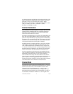
Use a 5–30 VDC external power supply for the output channels.
The power supply must provide enough current to power all of the
loads on the output channels, up to a maximum of 2 A per channel.
Connect the external power supply to multiple V and V
SUP
terminals and to multiple C and COM terminals as needed to
ensure that the maximum current through any terminal is 2 A
or less.
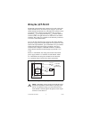
Install a 2 A maximum, fast-acting fuse between the external
power supply and the V
SUP
terminal on each channel. Install
a 2 A maximum, fast-acting fuse suitable for the load at the
V
OUT
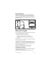
terminal. Figure 3 shows fuses where appropriate.
Figure 3. Wiring the [c]FP-PG-522
Caution
Maximum output current for the cFP-PG-522 is
temperature dependent. If the module is operating in the
60–70 °C temperature range, you must select fuses for
each channel so that the sum of the squares of the output
currents is lower than 8 A
2
.
To next channel
[c]FP-PG-522
+
–
V
OUT
V C
V
SUP
COM
V
SUP
Load
2 A max
5–30 VDC
External
Power Supply
Sinking
Output
Circuitry
2 A max