5
SETTINGS AND PROCEDURES BEFORE
OPERATION
5.2 CC-Link Safety Relay Module
5.2.3 Part names and settings
5 - 12
1
OVERVIEW
2
SYSTEM
CONFIGURATION
3
SPECIFICATIONS
4
FUNCTIONS
5
SETTINGS AND
PROCEDURES BEFORE
OPERATION
6
TROUBLESHOOTINGAPPENDIX
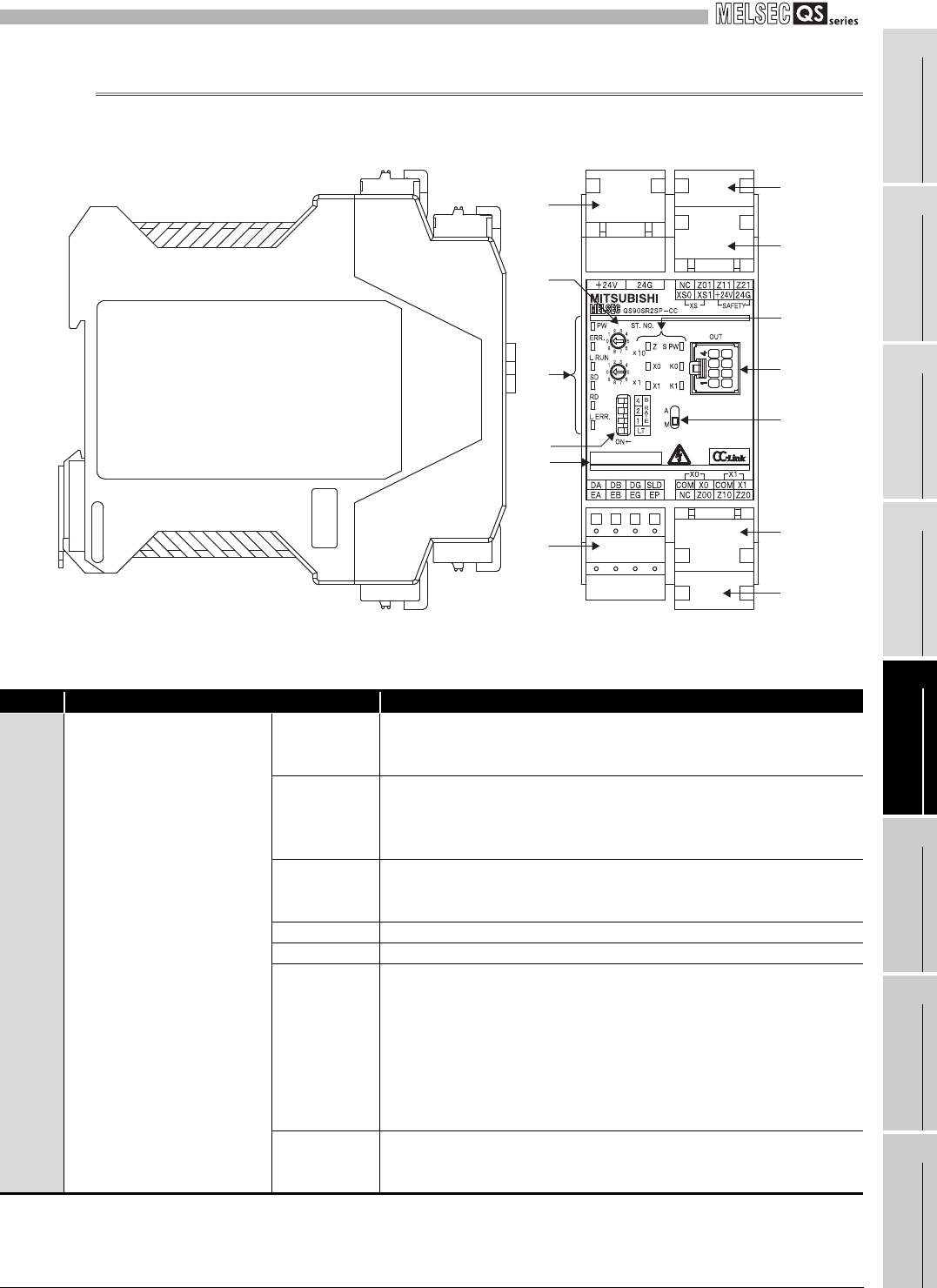
5.2.3 Part names and settings
This section explains each part name of the CC-Link safety relay module.
Figure 5.8 CC-Link safety relay module
Table 5.2 Part names (1/2)
Number Name
Description
1) Indicator LED
PW
Indicates status of the module power supply.
ON: Module power supply is supplied.
OFF: Module power supply is cut off or powered OFF with electric fuse.
ERR.
Indicates an error of the station.
Flash: A self-diagnostics error has occurred or safety power supply is cut
off.
OFF: Normal
L RUN
Indicates communication status of the CC-Link system.
ON: Normal communication
OFF: Communication is cut off (time over error).
SD ON: During data transmission
RD ON: During data reception
L ERR.
Indicates a communication error in the CC-Link system.
ON: A value set with station number setting switch or
transmission speed setting switch is out of range.
Flashing regularly: The station number setting switch or transmission
speed setting switch is changed during operation.
Flashing irregularly: A terminating resistor is not attached, is attached
wrongly or is influenced by noise.
OFF: Normal communication
S PW
Indicates the status of the safety power supply.
ON: Safety power supply is supplied.
OFF: Safety power supply is cut off or powered off with an electric fuse.
1)
7)
11)
3)
6)
8)
2)
5)
1)
9)
10)
4)
6)


