


3 - 15
3.6 Cable Specifications
3
SPECIFICATIONS
3.6 Cable Specifications
(1) Safety circuit part extension cables
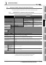
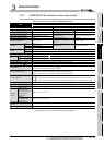
Table 3.9 shows the specifications of cables used for adding a safety relay module.
Use the following cable for adding the safety part.
If using a cable other than the following, the operation is not guaranteed.
(2) Monitor circuit part extension cables
Use shielded cables for the extension cable of monitor circuit part.
For the Q series safety relay module, connect the shield to SLD terminal on the
module, and for the CC-Link safety relay module, ground it from the control panel.
Not doing so may cause a malfunction due to noise.
(3) Safety part terminating connector
This is a connector attached to the Q series safety relay module and CC-Link safety
relay module.
When adding a module, remove the safety part terminating connector and attach it to
“OUT” side connector of the extension safety relay module on the last stage.
If the connector is not attached, the module does not operate.
(4) CC-Link dedicated cables
Use CC-Link dedicated cables for the CC-Link system.
The performance of the CC-Link system can not be guaranteed when any other
cables are used.
For the specifications or any other inquiries of CC-Link dedicated cables, visit the
website; CC-Link Partner Association: www.cc-link.org
Remark
Refer to the CC-Link cable wiring manual issued by the CC-Link Partner
Association.
Table 3.9 Cable specifications
Name Model Cable length
Safety circuit part extension
cable
QS90CBL-SE01 10cm
QS90CBL-SE15 1.5m